3-86
V
ARI
*L
ITE
®
-
VL4
W
ASH
L
UMINAIRE
S
ERVICE
M
ANUAL
CONFIDENTIAL 02.9628.0010
7-Oct-97
d. While holding up luminaire head with one hand, reach under
yoke bearing and disconnect black, 26-pin connector from
motherboard marked YOKE A MB-P4. Connector is
located next to connector marked YOKE B.
e. At rear of chassis, behind power supply, disconnect 26-pin
black connector from motherboard header marked YOKE B
MB-P5.
f. Remove yoke bearing frame from chassis.
Step 7. Remove motherboard.
a. At bottom left corner of motherboard, disconnect 5-pin
MTA connector from header marked DATA MB-P9.
b. At upper left of motherboard, disconnect 12-pin MTA
connector from header marked LVPS VIA VSB MB-P6.
c. At bottom right of motherboard, disconnect 4-pin MATE-
N-LOK connector from header marked UNREG. DC MB-
P8.
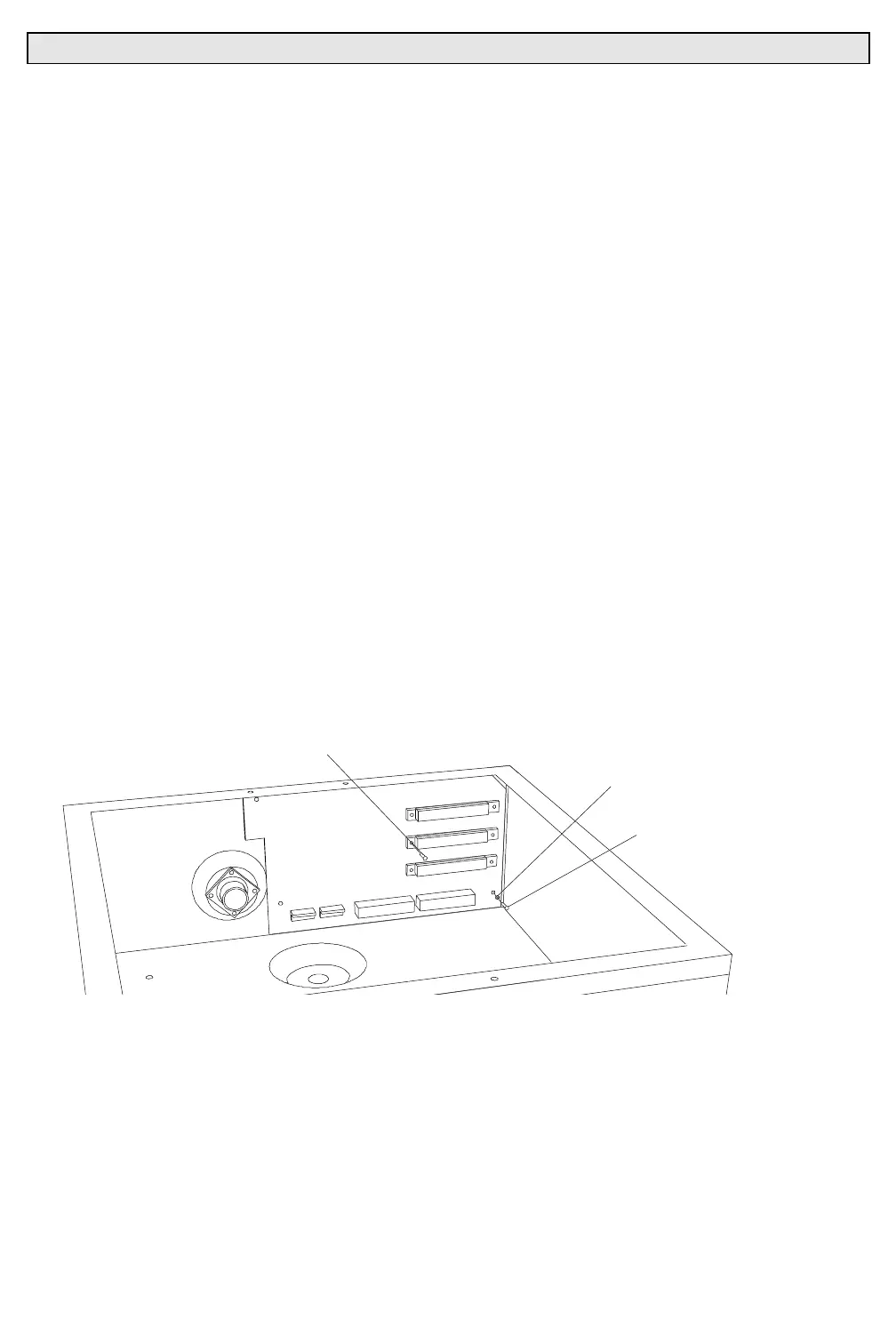
d. At motherboard corners, remove three 6-32x5/16"PPZ
screws and #6 internal tooth lockwashers (
Figure 3-32
).
e. At P1, P2, and P3 connector headers, remove total of six
4-40x3/8"PPZ screws that secure motherboard to chassis
and remove motherboard.
4-40X3/8"PPZ SCREW
#6 INTERNAL TOOTH
LOCK WASHER
6-32X5/16"PPZ SCREW
Figure 3-32. Motherboard Removal and Replacement
Step 8. Replace motherboard by doing Steps 2 thru 7 in reverse.