3-92
V
ARI
*L
ITE
®
-
VL4
W
ASH
L
UMINAIRE
S
ERVICE
M
ANUAL
CONFIDENTIAL 02.9628.0010
7-Oct-97
d. While holding up luminaire head with one hand, reach under
yoke bearing and disconnect black, 26-pin connector from
motherboard marked YOKE A MB-P4. (Connector is
located next to connector marked YOKE B.)
e. At rear of chassis, behind power supply, disconnect 26-pin
black connector from motherboard header marked YOKE B
MB-P5.
f. Remove yoke bearing frame from chassis.
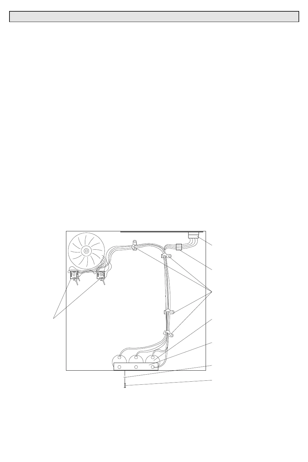
Step 7. Remove mounted capacitor assembly.
a. At chassis bottom, using diagonal cutters, remove cable ties
securing capacitor assembly to five cable anchors
(
Figure 3-35
).
b. At bottom right corner of motherboard, disconnect 4-pin
MATE-N-LOK connector from header marked UNREG.
DC MB-P8.
c. At bridge rectifiers, disconnect red, green, blue, and yellow
mounted capacitor assembly spade connectors.
d. At capacitor bracket, remove two 6-32x5/16"PPB screws
and #6 lock washers that secure bracket to chassis.
CABLE
ANCHORS
MOTHERBOARD
CONNECTOR
UNREG. DC
MB-P8
ADHESIVE BACIKED
CABLE ANCHOR
MOUNTED
CAPACITOR
ASSEMBLY
#6 INTERNAL TOOTH
LOCK WASHER
6-32X5/16"PPB SCREW
CAPACITOR
MOUNTING
BRACKET
WIRINGVW
BRIDGE
RECTIFIERS
GREEN
RED
YELLOW
BLUE
Figure 3-35. Mounted Capacitor Assembly Removal and Replacement