3-38
V
ARI
*L
ITE
®
-
VL4
W
ASH
L
UMINAIRE
S
ERVICE
M
ANUAL
CONFIDENTIAL 02.9628.0010
7-Oct-97
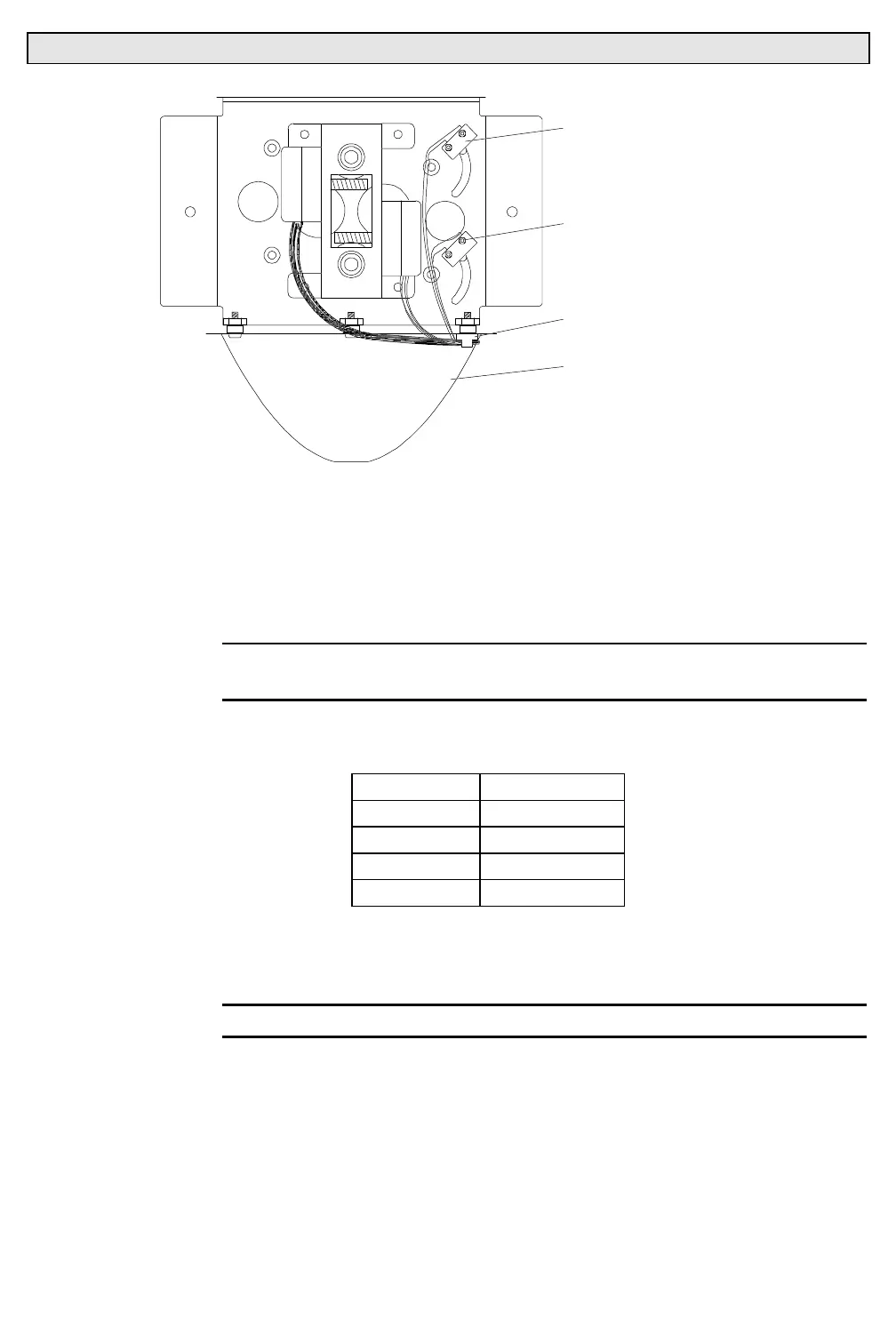
SENSOR
REFLECTOR
CABLE ANCHOR
2-56 NYLON INSERT
STOP LOCK NUT
BATOP
Figure 3-3. Blue/Amber Bulkhead Assembly Sensor Removal and Replacement
Step 4. Prepare replacement sensor.
a. At replacement sensor assembly, using needle-nosed pliers,
bend unused sensor lead to 45 degree angle.
b. Trim sensor assembly wires to 15 inches.
CAUTION
: To avoid poor connections, do not reuse MTA connector
from removed sensor on replacement sensor.
c. Using MTA crimper, crimp wires into new 4-pin MTA
connector using the following pinouts:
Pin Wire
4 Blue
3 Blue
2 N/C
1 N/C
d. Install strain relief cover on 4-pin connector. Using
permanent ink marker, mark strain relief either BLUE or
AMB as necessary.
CAUTION
: Do not overtighten nuts when installing replacement sensor.
e. Install replacement sensor and re-install blue/amber
bulkhead by doing Steps 2 and 3 in reverse.