C
HAPTER
3. M
AINTENANCE
P
ROCEDURES
3-51
02.9628.0010 CONFIDENTIAL
7-Oct-97
Step 4. Prepare and install replacement sensor.
a. At replacement sensor assembly, using needle-nosed pliers,
bend unused sensor lead to 45° angle.
b. Trim sensor assembly wires to 17 inches.
CAUTION
: To avoid poor connections, do not reuse MTA connector
from removed sensor on replacement sensor.
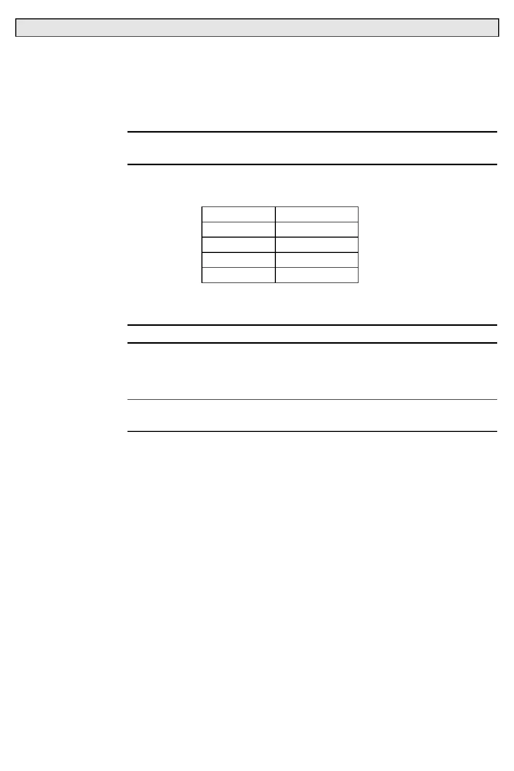
c. Using MTA crimper, crimp wires into new 4-pin MTA
connector using the following pinouts:
Pin Wire
4 Blue
3 Blue
2 N/C
1 N/C
d. Install strain relief cover on 4-pin connector. Using
permanent ink marker, mark strain relief as MAG.
CAUTION
: Do not overtighten nuts when installing replacement sensor.
e. Install replacement sensor and re-assemble
dimmer/filter/douser assembly by doing Steps 2 and 3 in
reverse.
Note
: During installation of sensor, make sure that sensor is installed with
microswitch pointing towards honeycomb.