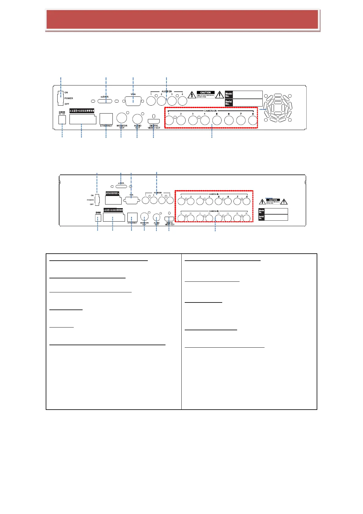
1.Power Switch(Only the 4CH HYBRID-DVR)
Switch to turn the DVR ON & OFF.
2.eSATA Connection Port(Option)
connect e-SATA storage to expand HDD
3.VGA Output (Video Graphic Array)
15-pin D-sub connector for the analogue VGA output.
4.Audio Inputs
RCA connectors for the audio signal inputs. (Line In)
5.Power In
12V DC Power socket.
6.Alarm(Sensor) Inputs, RS-485, and Relay Output
Alarm inputs x 4
RS-485 Signals. (G: Ground, D+: RX/TX + signal, D-:
RX/TX- signal)
4CH HYBRID-DVR: Relay output for the relay 1 (NO:
Normal Open, NC: Normal Closed, CM: Common)
8&16CH HYBRID-DVR: Relay output for the relay 2
(NO: Normal Open, NC: Normal Closed, CM:
Common)
7.RJ-45 Network Port( 1G Base-T)
Network port is used to 1G base-T, PC applicatio
n software or Mobile application.
8. CVBS Monitor Output
Composite video output for the spot live screen.
(BNC)
9.Audio Outputs
RCA connectors for the audio signal outputs. (Line
out)
10.DIGITAL VIDEO OUT
Digital video output for the main monitor.
11. HD-SDI or Analog Camera Input
analog Camera input or HD-SDI video inputs for e
ach camera