7. Thread all required cables through one of the conduit entries.
For Outdoor
Installation
Using
Perform the following:
Cable Gland a. Insert the rubber ring into the cable gland.
b. Loosen the thread-lock sealing nut of the cable gland.
c. Thread all required cables through the sealing nut and
the gland body.
d. Fasten the gland body to one of the conduit entries.
e. Tighten the thread-lock sealing nut to the gland body.
f. Seal the end of the thread-lock sealing nut with RTV
silicon. Ensure that there are no gaps between the
sealing rubber and the cables.
¾ inch
NPTPipe
a. Apply the Teflon tape to the threads of the pipe.
b. Attach the pipe to the camera conduit entry.
c. Thread all required cables through the pipe.
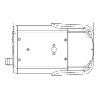
8. Connect the cables to the camera.
9. Reattach the camera to the metal mounting plate.
10. Adjust the pan / tilt / spin holders to point the lens at a suitable position for
the desired camera view.
11. Replace the silica gel pack below the BNC connector with the new silica gel
provided to prevent moisture inside the camera.
12. Reattach the dome cover.
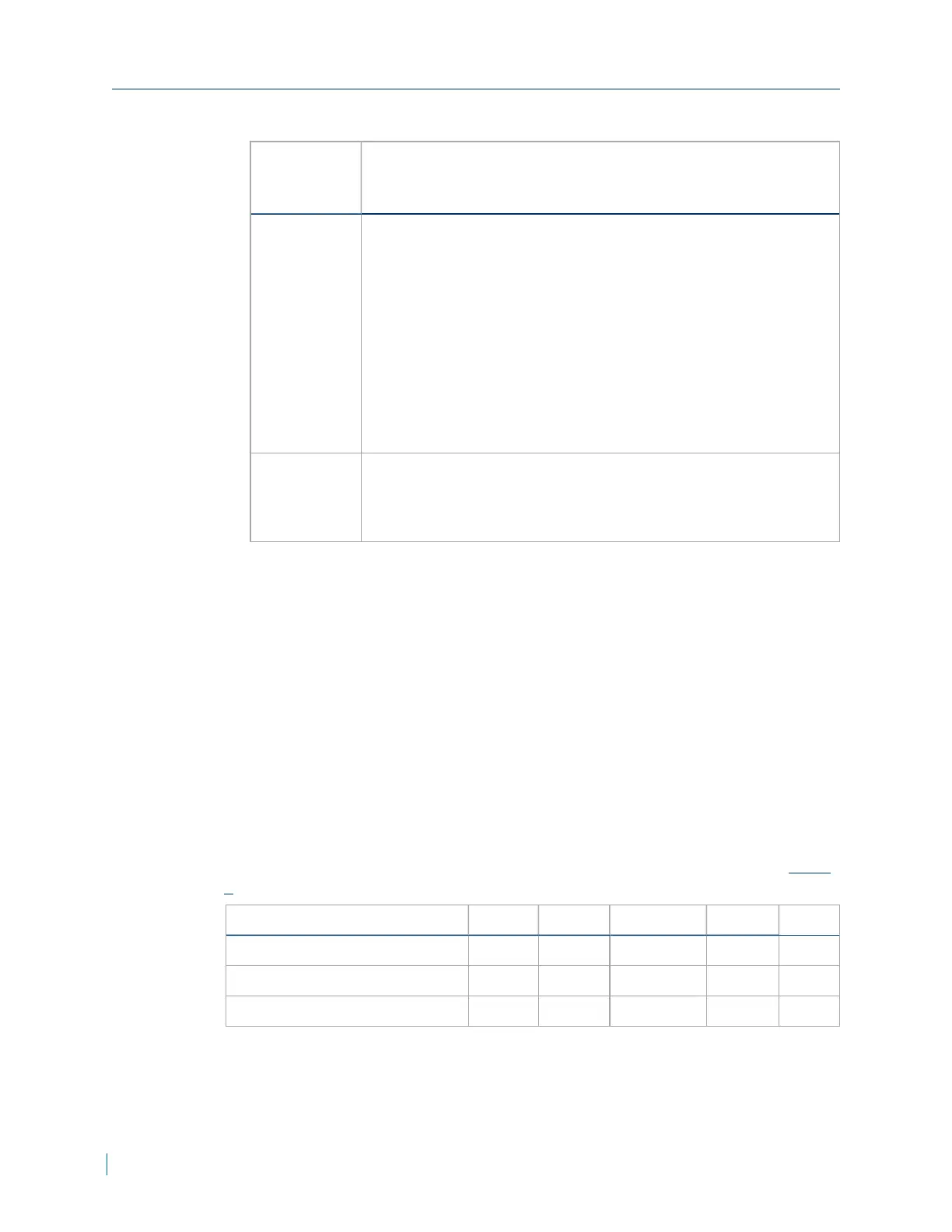
Nominal Power Consumption Values
The following table lists the nominal power consumption in Watts that the
cameras require to operate under standard conditions. See the "Safety" (page
5).
Nominal Power Consumption System IRLEDs Lens Motor Heaters Total
V4320BX 6.3W N/A N/A N/A 6.3W
V4320FD 5.6W 3.6W 3.2W N/A 12.4W
V4320FDW 5.6W 3.6W 3.2W 7W 19.4W
Nominal Power Consumption Values
16 © 2014 Verint Systems Inc. All Rights Reserved Worldwide.
 Loading...