In the edit state, click (5) Restore System button to restore the default; click (7) Same type of equipment
effectively button to batch configure other devices of the same type; click (6) Save button to save; click (4) Back to
Browse button to convert page to browsing status.
Notices
1. The overview page has different default control display modes according to different device types, and the default is restored
to this state.
2. Some types of devices have specific state diagrams that are not removable and not configurable. They can only update state
map location information, such as air conditioners, UPS, and so on.
2) Sampling
Click the Sampling tab to enter the acquisition signal page to display the acquisition signal of the selected device, as
shown in the Figure 3-43.
Figure 3-43 Acquire the Signal
If a signal is in an alarm state, the line of the signal is displayed in red, as shown in the "Rear door" signal.
3) Control
Click the Control tab and go to the Control Signals page to display the control signals for the selected device, as
shown in the Figure 3-44.
Figure 3-44 Control signal
Select an item in the drop-down box for the Set Value and then click the Set button to control the device.
Notices
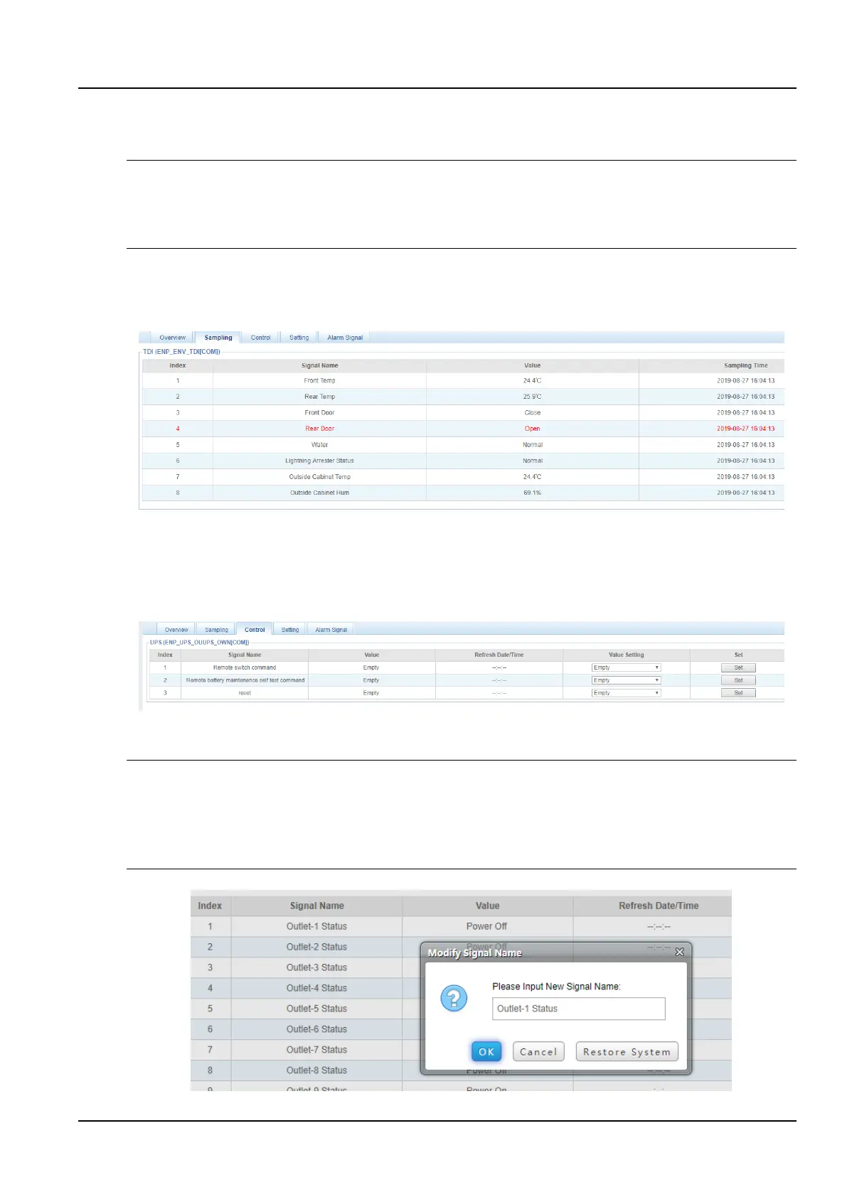
1. The name of each independent port can be customized on the PDU control page.
2. Open the PDU control signal page, as shown in Figure 3-44.
3. Click an Outlet-X status (Outlet-1, Outlet-2, ...) in the signal name column, so that a signal name modification dialog box is
displayed, as shown in Figure 3-45.
4. Enter a self-defined port name in the dialog box and click OK to complete the self-defined setting of PDU port name.
Figure 3-45 Port Name Modification Dialog Box