To connect two or more cooling units into one group (maximum of 32 units per group, up to 99 groups), a network switch is
required.
• On each unit, connect one end of an Ethernet cable to the P64 connector on each Vertiv™ Liebert® iCOM™
control board, and the other end to the U2U network switch, see Figure 13.16 below .
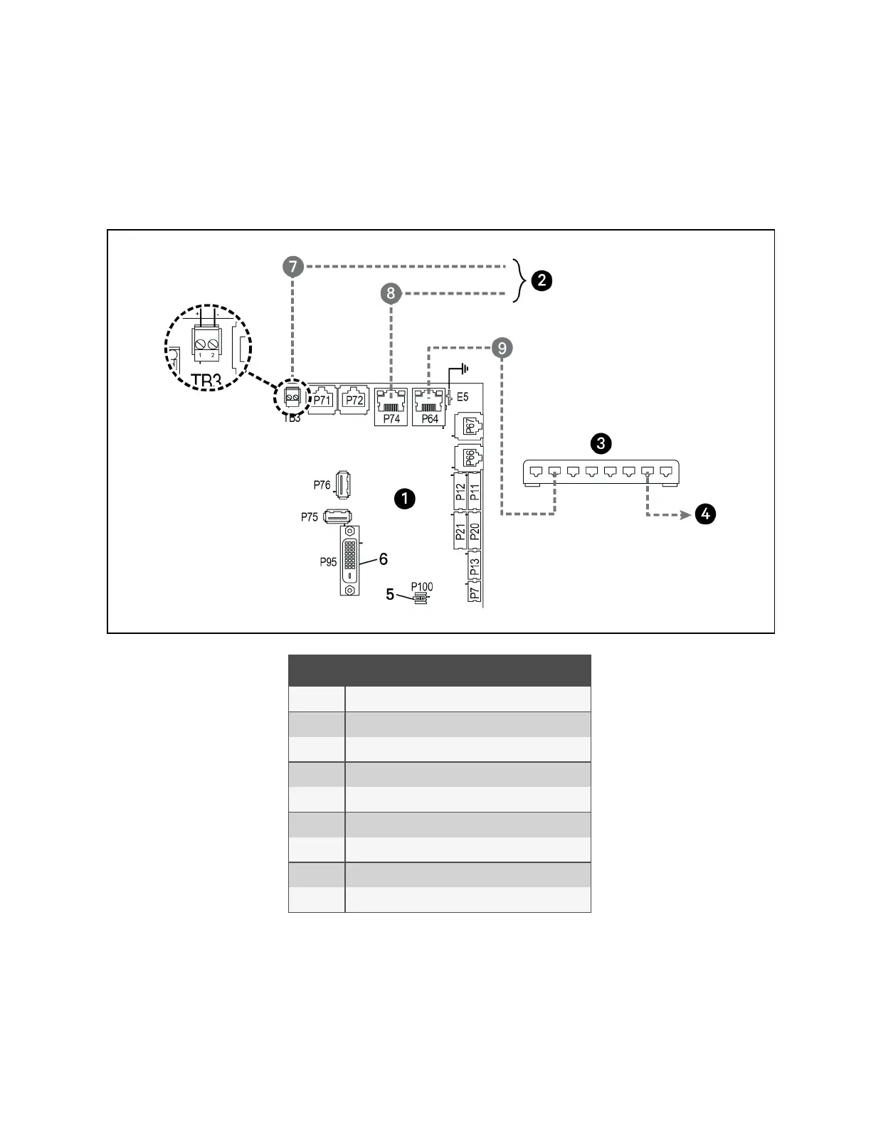
Figure 13.16 Connecting Two or More Units with a Network Switch
Item Description
1 Liebert® iCOM™ microprocessor and I/O board
2 Site and BMS communication connections
3 Network switch (field supplied)
4 To/From other networked units
5 P100, power supply to Liebert® iCOM™ display
6 P95 DVI-D cable connection to Liebert® iCOM™ display
7 RS485 cable
8 Ethernet cable
9 Ethernet cable (field supplied)
13 Vertiv™ Liebert® iCOM™ Hardware Installation
200
Vertiv™ Liebert® iCOM™Installer/User Guide