030624.13 15
vetus® Electronic engine remote control
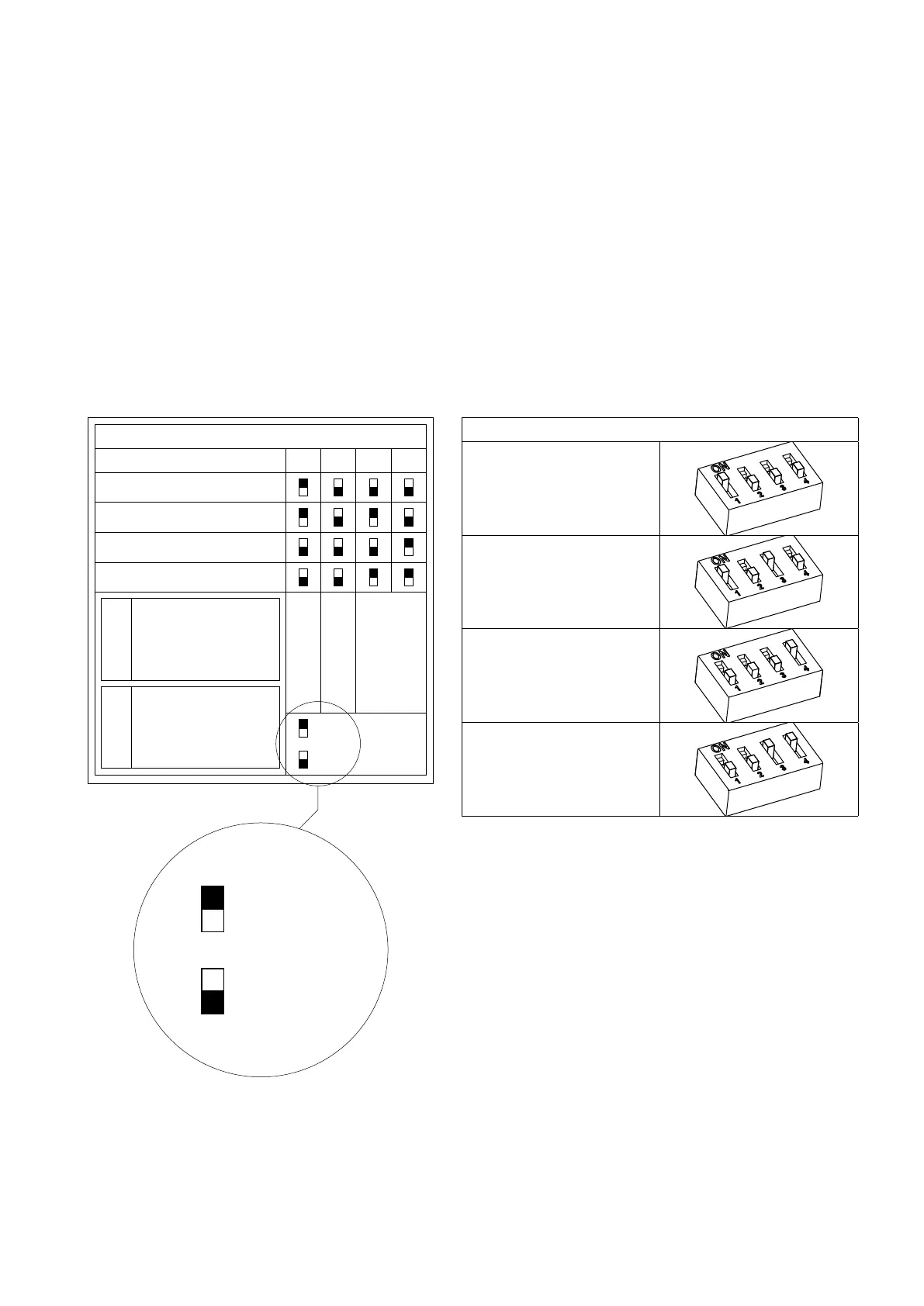
DIP switch configuration
1 2 3 4
Command station 1
Command station FSM
Command station 2
Command station 3
CodeS/N
Line termination
Trolling
Address
ON
OFF
4.4 Command station label
There is a label under the base of the command station.
This label shows the code and the serial number of the command station. The dip-switches configure the control station
on the base of its position in the CANBus network. The dip switch selector is represented with a small black square.
Command station 1, Command station 2, Command station 2 and Command station FSM are different addresses on the
CANBUs network.
If there are multiple stations in the same system, each one must have a different address. “Command station FSM” and
“Command station 1” cannot coexist in the same installation. “Command station FSM” is an alternative to “Command
station 1” and vice versa.
Chapter 7 lists the most common types of systems, which can only be configured with a correct dip-switch setting. 4.5.
Trolling option
ON
OFF
Dip-switch configuration details
Command station 1
Command station FSM
(Fast Start-up Mode)
Command station 2
Command station 3
4.5 Trolling option
To activate the Trolling function, dip-switch 2 must be set to ON. For specific information refer to the document “Troll-
ing_Flap option for lever EC3 & EC4”.