030624.13 37
vetus® Electronic engine remote control
The actuator configuration changes according if the system is with one or two actuators:
Installations with 1 actuator Installations with 2 actuators
JP14 = OFF (address = 0)
Left actuator is with JP14 = OFF (address = 0)
Right actuator is with JP14 = ON (address = 1)
The settings of JP14 and JP19 depend on the configuration of the CANBus network, as described from
section 7.1 to 7.5
7.6.2 Configuration of the actuator
To configure the actuator it is necessary to:
• enable or disable the end of line resistor
• define the CANBus address
These operations must be according to the position of the actuator as described in the schemes of chapter 7.
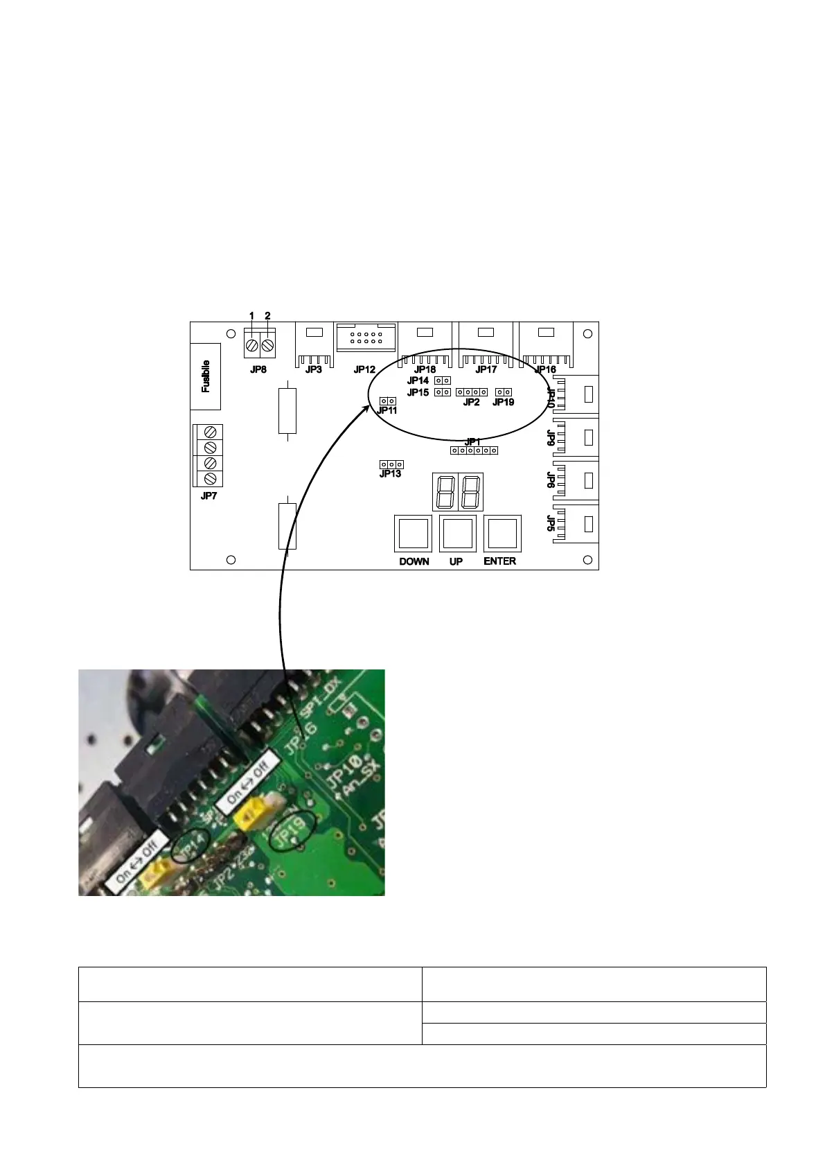
Actuator PCBoard version 3.1
JP14 defines the CAN Bus address of the actuator. Factory setting is JP14 = OFF (address =0).
JP19 enables (ON) or disables (OFF) the line termination. Factory setting is JP19 = ON (line termination = ON).
If JP14 = ON, address = 1
If JP19 = ON, end of line is enabled
In some documentation, alternative to ON or OFF are indicated YES or NO.