40 030624.13
vetus® Electronic engine remote control
8.1.2 The ignition key switch
Starter motors
The cables that connect the battery to the starter motors must have a cross-section of at least 50 mm
2
(both the
“plus” and the “minus” cable). The “minus” cable of the actuator must be connected directly to the battery. It is vital
that there is zero voltage between battery negative terminals.
Electronic system with 1 actuator
In case of 2 batteries, the actuator must be connected
to both the batteries. The “plus” cables must be con-
nected with a 10A decoupling diode. In this way the
actuator will be supplied by the most charged battery.
The minimum section of the cable must be of 2,5 mm
2
.
Electronic system with 2 actuators
Each actuator must be supplied from its own battery.
The minimum section of the cable must be of 2,5 mm
2
.
Refer to electrical installation scheme reported in sec-
tion 8.1.3 for system with one ignition key and 8.1.4 for
system with two ignition keys. This last scheme allows
to power the actuator box activating at least one of
the two ignition keys.
If your application has double deck (e.g. main deck
and fly-bridge) refer to installation scheme reported in
section 8.1.5.
Refer to electrical installation scheme reported in sec-
tion 8.1.6.
If your application has double deck (e.g. main deck
and fly-bridge) refer to installation scheme reported in
section 8.1.7.
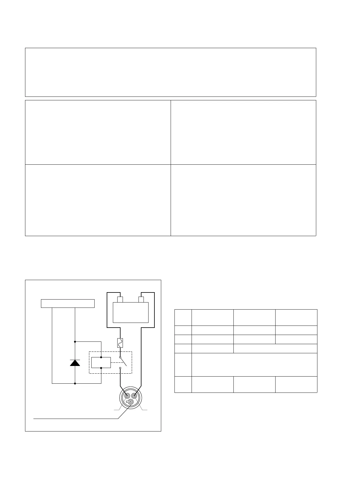
8.1.3 Electrical installation of systems with 1 engine, 1 actuator and 1 ignition key
Ref. Description
12 V power
supply
24 V power
supply
D Diode 10 A, 20 V 5 A, 24 V
R Relay 10 A, 12 V 5 A, 24 V
F Fuse 10 A
15
Terminal 15 is the signal coming from the igni-
tion key lock. When the ignition key is on its rst
detent, signal 15 is active.
Supply cable
cross section
2,5 mm
2
1,5 mm
2
R
L
N
+
-
F
A1
A2
Com
NO
D
Battery
Ignition key
- Battery
Signal 15
Actuator power supply connector