030624.13 69
vetus® Electronic engine remote control
12.3 Specific parameters
Display
code
Description Values
Factory
value
Value shown on dis-
play (factory value)
Note
A0 Push-pull cable movement direction 1 .. 4 4 04
dI Delay before disengaging the gearbox 0 .. 9,9 s 0,0 s 00
dA Delay on the throttle 0 .. 9,9 s 0,0 s 00
PP Proportional coefficient 0 .. 99 40 40 These parame-
ters must not be
changed
PI Integral coefficient 0 .. 99 0 00
CP CANBus protocol 1-99 0 00 See 15.2.2.
L1
These parameters are present only in systems with electronic engine (ECU) and/or
electrical engine inverter driven. Parameters to define the voltage output interface will
be detailed at section 12.3.2.
H1
L2
H2
L3
H3
L4
H4
CC To be used for the check-up of the internal CANBus communication
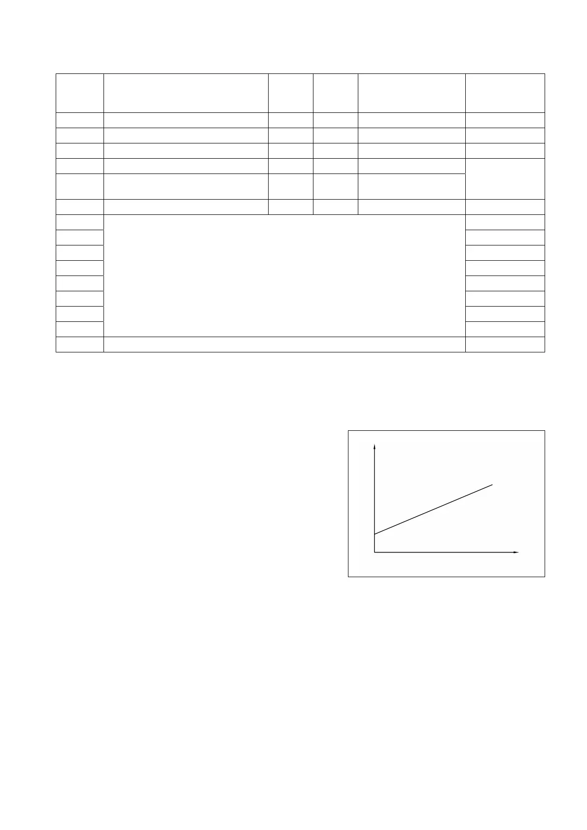
12.3.1 Parameters to configure the voltage output signal for electronic engines
For installations with electronic engines or hybrid propulsion sys-
tems (engine driven by a frequency converter), it is necessary to set
the minimum and maximum voltage output. Voltage signal profile
is defined through parameters L*, and H*, where “*” means 1,2,3,4.
Important: the graphic on the right represents the voltage profile
defined by parameters L, H. Changes of factory values could cause
a system malfunctioning. Before making any changes, contact our
technicians.
V
L*
H*
Control lever stroke
 Loading...