30 030624.13
vetus® Electronic engine remote control
7 Configuration of the CANBus network
System types, installation schemes and addressing for command stations and actuators
How to configure the installation depends from the quantity, type of engines and gearboxes and number of command
stations. Actuators and command stations, which communicate together through the CANBus network, must be config-
ured in relation to how they are connected to the CANBus network. In the following installation schemes you find:
• Components necessary to build an installation
• Configuration of actuators and command stations in relation of their position on the CANBus network
The following installation schemes cover the most common application cases.
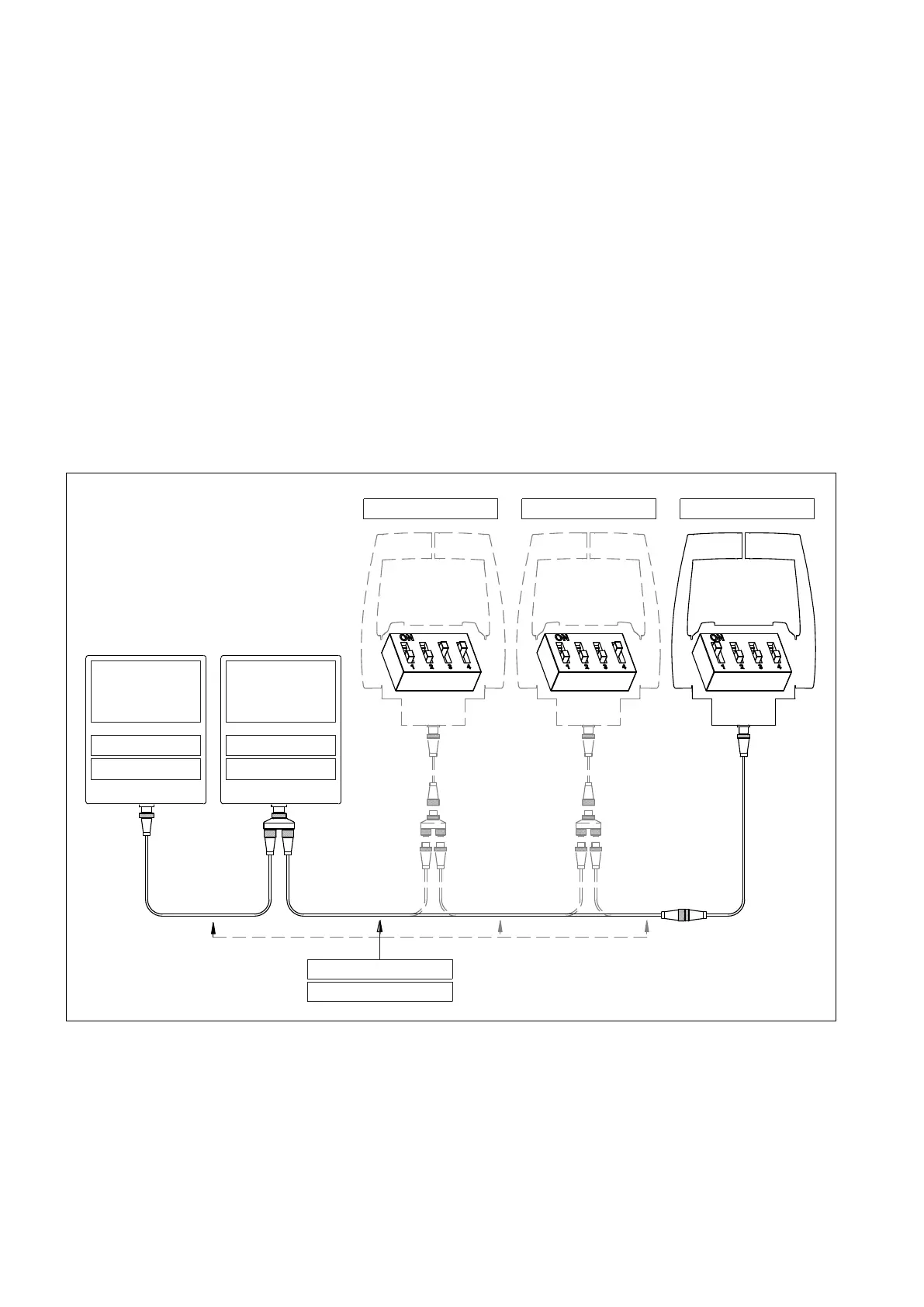
7.1 Installation with 2 mechanical actuators – solution A
This installation scheme is valid for systems with:
• Up to 3 command stations and 2 engines with mechanical throttle, mechanical gearbox, with/without trim;
Code: DTCANxx
JP19: ON (end-line) JP19: OFF (end-line)
JP14: ON (address)
JP14: OFF (address)
Actuator for
left engine
Actuator for
right engine
Command station 1Command station 2Command station 3
Data transmission cable