50 030624.13
vetus® Electronic engine remote control
9.3 Actuator parameters
Parameters are different in relation of the type of actuator and application. The detailed parameter list for each applica-
tion is described in the specific section reported in the following pages. Here below are listed the parameters common
for any type of actuator.
Code
display
Description Range Factory
value
Value shown on dis-
play (factory value)
Note
A0 Push-pull cable movement direction 1 .. 4 4 04
dI
Delay before disengaging the gear-
box
0 .. 9.9 s 0.0 s 00
dA Delay on the throttle 0 .. 9.9 s 0.0 s 00
CC To be used for the check-up of the internal CANBus communication
A0 is described in section 11.2
With parameters dI and dA it is possible to set a delay time measured in tens of seconds:
• dI is the delay that occurs when you move the lever from forward (or reverse) to neutral. The actuator goes to neutral
only after the time set into dI expires.
• dA is the delay that occurs when you move the lever from neutral to forward (or reverse). The actuator starts to accel-
erate only after the time set into dA expires.
With parameter CC you can check if the communication between the command station and the actuator is correct. The
value of the parameter corresponds to a precise physical position of the lever and it is described in the following table:
Value shown on display Description
N indicates that the command station is in neutral position
F indicates that the command station is in forward position
R indicates that the command station is in rear position
1-2-3-4-…..-9-A
indicates that the command station is in throttle condition: “1” is the position of
minimum gas and “A” is the position of maximum gas
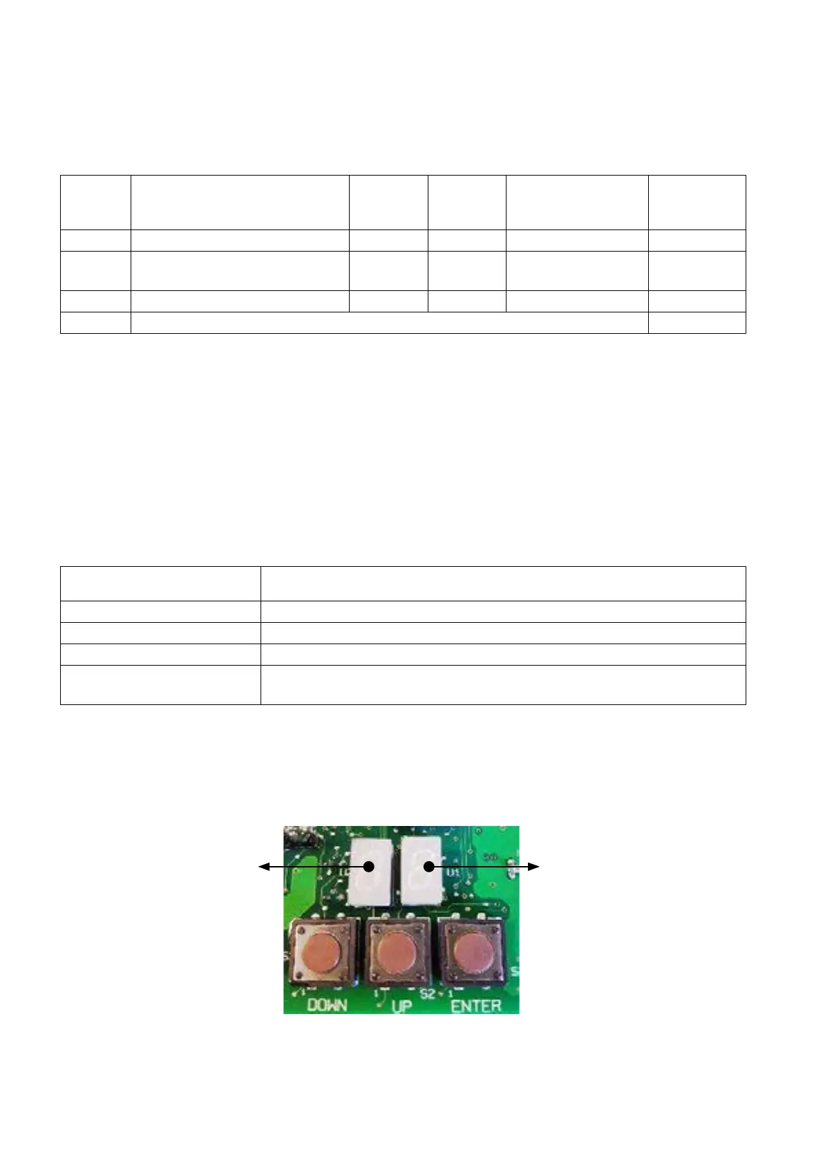
Looking at the display like in the picture here below, the left digit of the display shows the position of the left command
station and the right digit of the display shows the position of the right command station.
It is shown right lever position
according to the table above
It is shown left lever position
according to the table above