44 030624.13
vetus® Electronic engine remote control
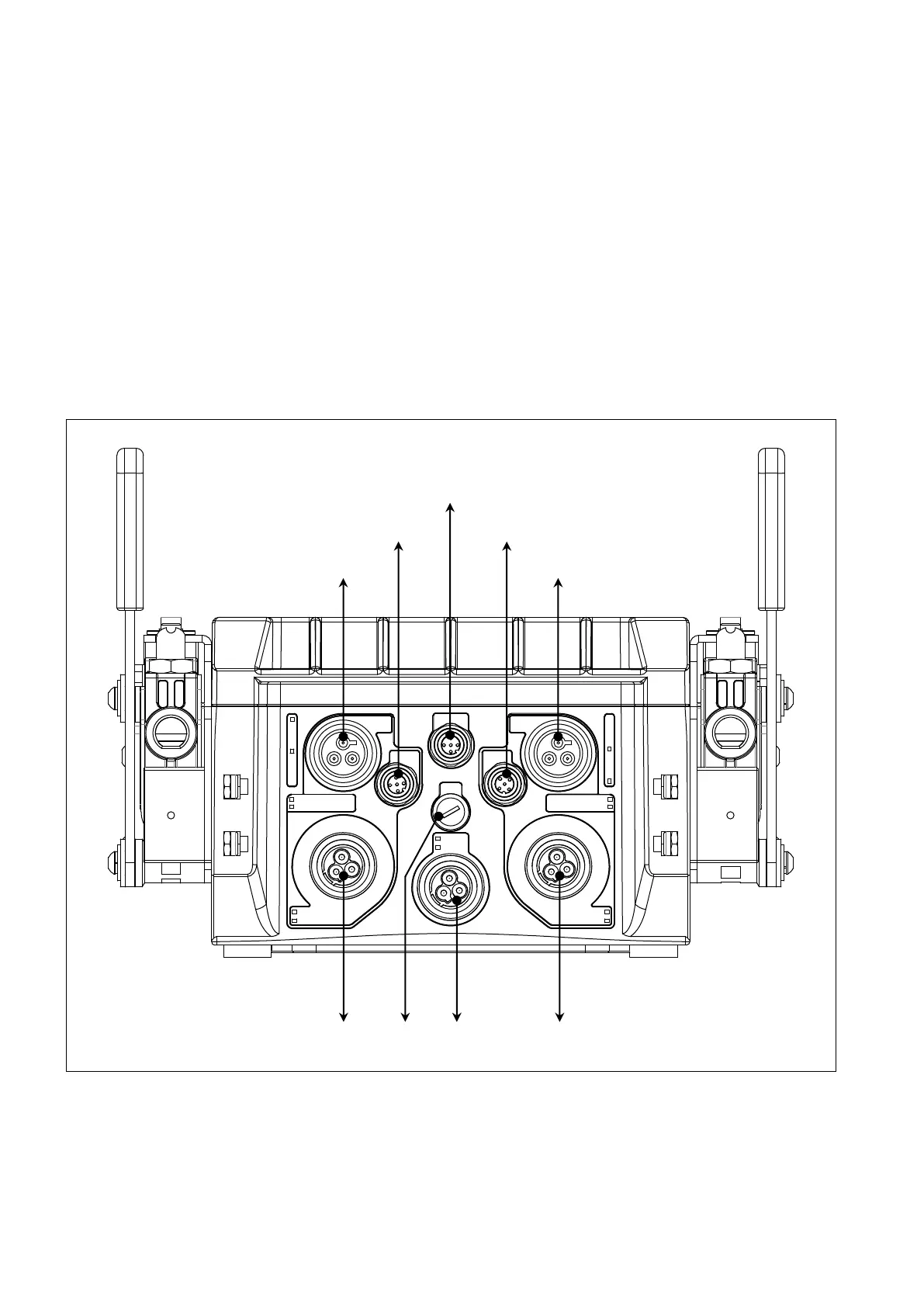
8.2 Wiring from the actuator to command stations, engines, gearboxes, trim/flaps, etc (out-
put cables)
Almost every cable is provided with its unique connector, therefore it is easy to identify the cable type, its function and
where to mount it. Each connector has a different polarization, so it is almost impossible to mount a cable in the wrong
position. For the description of all the types of cables, look at chapter 6.
When mounting the electronic engine cable on the actuator: align the polarization keys and insert carefully the M12
connector of the cable on the actuator M12 counterpart. Rotate then the M12 ring until the cable enters completely into
the counterpart. If the cable has been inserted correctly, it must be possible to screw completely by hand the cable with-
out too much efforts (around 6 full rotations). For more info look at chapter 6.
There are basically 4 types of actuators classified on the type of interface (mechanic or electronic) and on the type of
connector placed on the actuator itself (with or without neutral relay).
8.2.1 Actuator with mechanical interface without neutral relay
For better comprehension are depicted only the electrical connections and not the mechanical linkages. This actuator is
available in versions with neutral relay, with or without trim and it is suitable for the following applications:
• mechanical engine and mechanical gearbox (only 1 propulsion group per actuator)
• mechanical engine and solenoid driven gearbox (2 propulsion groups per actuator)
• electronic engine and mechanical gearbox (2 propulsion groups per actuator)
ThrottleGear
ThrottleGear
+12 V
+24 V
Trim
Flap
Trim
Flap
Gear
Neutral switch
Gear
Neutral switch
Mech left engine
Ein left engine
Mech left engine
Ein left engine
Canbus
Throttle Throttle
Left gearbox
Left engine - Trim/Flap
Left engine - Throttle
CANBus to the comman station
Left engine - Throttle
Right engine - Trim/Flap
Right gearboxFuse Supply