VIVOTEK - Built with Reliability
16 - User's Manual
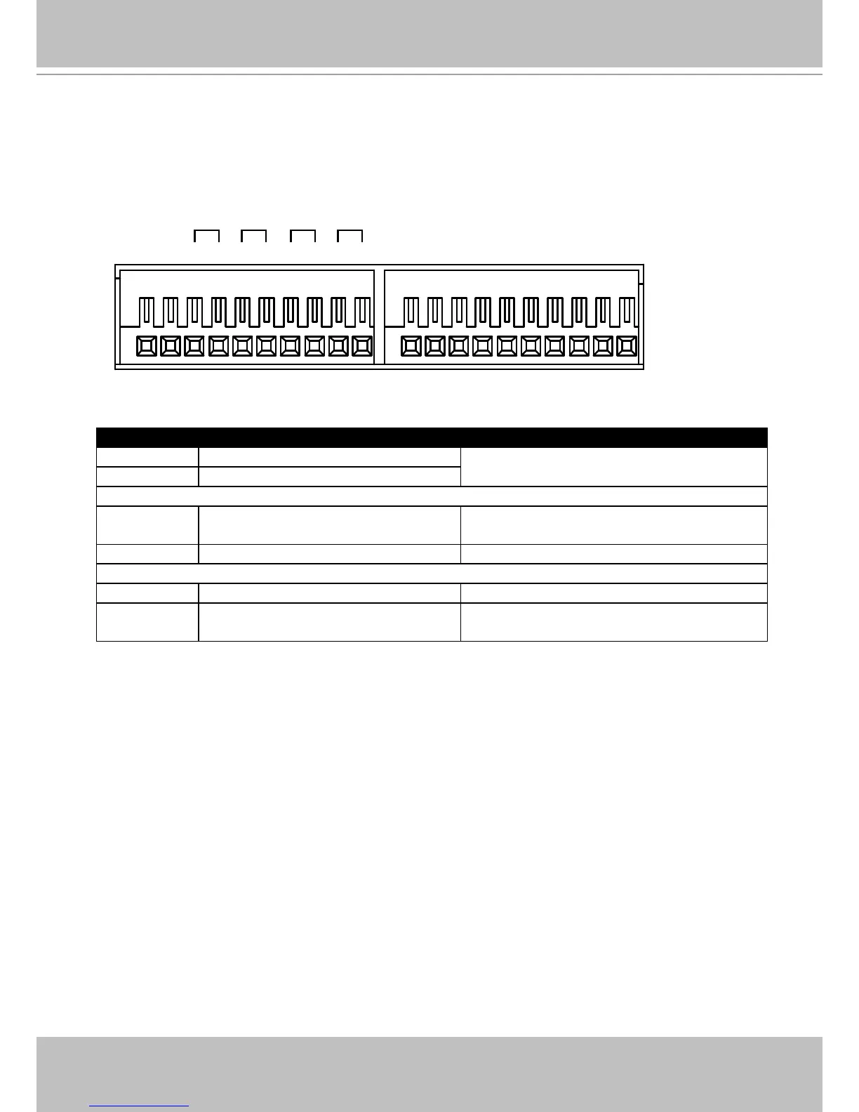
Terminal Block Connections
The terminal block pinouts is shown as follows:
RS485
+-
4 3 2 1
Alarm OUT
G 8 7 6 5 G 4 3 2 1
Alarm IN
DO+DO- DO+DO- DO+DO- DO+DO-
The pins are listed and described from left to right as shown in the drawing above.
Pin Description NOTE
RS485- RS485 Data- A 120Ω terminator is enabled on the bus.
The terminator cannot be disabled.
RS485+ RS485 Data+
Alarm OUT
DO+ DC 12V±5% output, max. 40V,
50mA. Open collector design.
DO- Signal ground
Alarm IN
DI no. 1 ~ 8 Open-short-to-GND
G Pins #1~4 share a common ground.
Pins #5~8 share a common ground.