Chapter 5: Detailed description of parameters
141
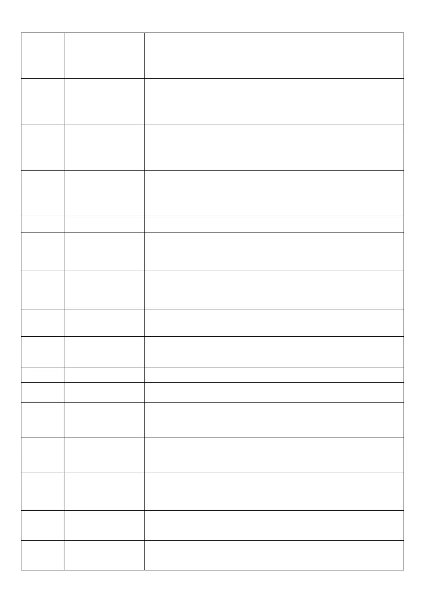
The cumulative
operating time
reached
If the cumulative runtime exceeds the time set in P8.17, the
output is ON.
If the set frequency exceeds the upper or lower frequency
limit and the output frequency of the inverter reaches the
upper or lower limit, the output is ON.
In torque control mode, if the output torque reaches the
torque limit, the inverter enters the protection state and the
output switches ON.
The inverter is
ready to RUN
If the main circuit and the control circuit are stable and the
inverter detects no fault and is ready for RUN, the output
will be ON.
When the FIV input is greater than the FIC input, the output
is ON.
The upper
frequency limit
reached
If the frequency of RUN mode reaches the upper limit, the
output is ON.
The lower
frequency limit
reached
If the frequency of RUN mode reaches the lower limit, the
output will turn ON. In the event of a stop, the output will
switch off.
If the inverter is under voltage, the output will turn ON.
See the communication protocol.
If the output frequency of the inverter is 0, the output is ON.
In the event of a stop, the output is still on.
Total time under
voltage reached
If the cumulative turn on time of the inverter (P7.13)
exceeds the value set in P8.16, the output is ON.
Detection of the
FDT2 frequency
level
See description P8.28 and P8.29.
See description P8.30 and P8.31.
See description P8.32 and P8.33.


 To Next Page