5-90 BA 357-00 * 3.0 * 35700_05_Bedienung.fm
5 Operation
Load diagram for pallet forks
The load diagram in the cabin is only valid for applications with the
released pallet forks
– see chapter 9 “Payload/lift capacity/stability” on page 9-18!
The load diagram is located inside the cabin on the left of the front window
or on the front trim.
Observe the load diagrams of other attachments (attachments from other
manufacturers) used, or calculate them
– see "Fitting attachments from other manufacturers (opt)" on page 5-95!
Tipping hazard of machine due to failure to pay attention to the load
diagram!
Can cause serious injury or death.
► Do not exceed the maximum loads stated, otherwise machine stability
is no longer ensured.
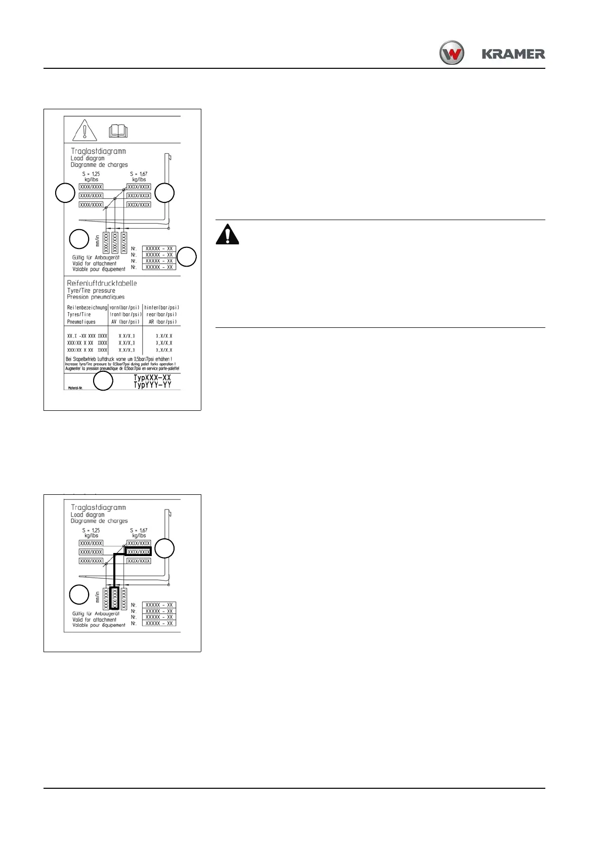
• To determine which vehicle the attached load diagram applies, see
specifications in area D.
• To determine which attachment the attached load diagram applies, see
specifications in area E.
•Area A shows the maximum loads for applications
on level ground (stability S = 1.25).
•AreaB shows the maximum loads for off-road
applications (stability S = 1.67).
• The maximum load is a function of the distance between (area C)
to the fork frame.
Important! Also take the maximum load into account when using fork
arm extensions!
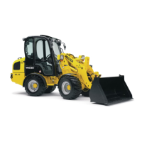
Example:
• At a load distance C of 600 mm (23.62 in), the maximum load B for
off-road applications is 1200 kg (2646 lbs)!