3-34 BA 357-00 * 3.0 * 35700_03_Einleitung.fm
3 Introduction
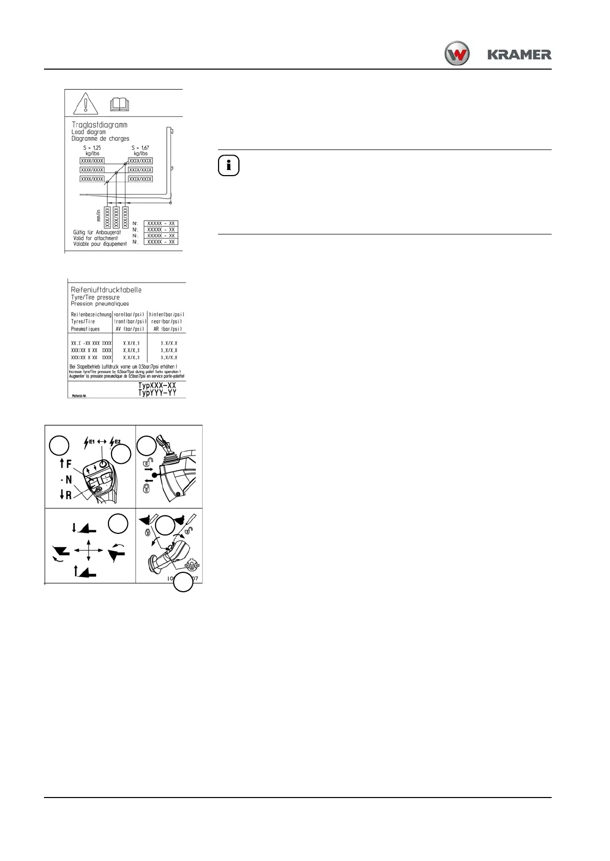
Load diagram
The load diagram indicates the maximum payload for the attachment
– see chapter 9 “Payload/lift capacity/stability” on page 9-18.
Located inside the cabin, on left side of front window.
The load diagram is valid only for applications with the released pallet
forks and corresponding tire size. Pay attention to the specific load
diagrams of other attachments used
– see chapter 5 “Load diagram for pallet forks” on page 5-90.
Tire pressure table
The label contains a list of certified types of tires with mandatory tire
inflation pressures – see chapter 9 “” on page 9-6.
Located inside the cabin, on left side of front window.
Operation of control level (joystick)
with switch for 3rd control circuit
The label indicates the functions of the joystick control elements.
A Travel direction: (F) forward, (R) reverse and (N) neutral position
B Push button ON/OFF – power supply front power outlet (option)
C Joystick – raise, lower, and tilt in/out loader unit
D Mechanical control lever lock (joystick) for road travel
E Switch – 3rd control circuit: unlocking and locking the attachments on
the quickhitch and hydraulic control circuit for attachments
F Differential lock (option)
For more information on loader unit operation
– see chapter 5 “Operating hydraulics” on page 5-30.
Located on the right on the side window.