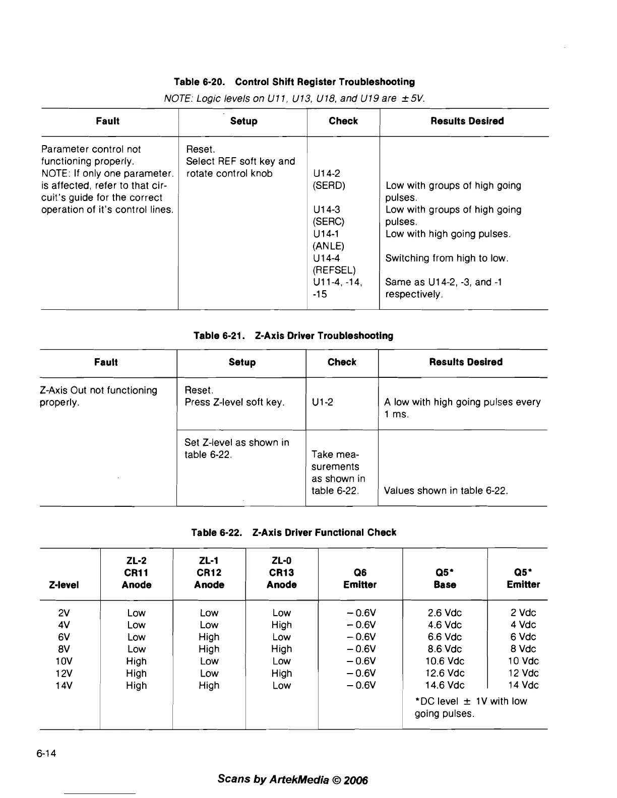
Table 6-20. Control Shift Register Troubleshooting
NOTE:
Logic
levels on
U
1
1,
U
13,
U
18,
and
U
19
are
2
5V.
Parameter control not
functioning properly.
NOTE: If only one parameter.
is affected, refer to that cir-
cuit's guide for the correct
operation of it's control lines.
Fault
Reset.
Select REF soft key and
rotate control knob
Setup
1
Check
1
Results Desired
U
1 4-2
(SERD)
U 1 4-3
(SERC)
U 14-1
(AN LE)
U 1 4-4
(REFSEL)
U11-4, -1 4,
-1
5
Low with groups of high going
pulses.
Low with groups of high going
pulses.
Low with high going pulses.
Switching from high to low.
Same as
U14-2, -3,
and
-1
respectively.
Table 6-21. 2-Axis Driver Troubleshooting
I
1
ms.
Z-Axis Out not functioning
properly.
Set Z-level as shown in
table
6-22.
Fault
Take mea-
surements
as shown in
table
6-22.
Check Setup
Reset.
Press Z-level soft key.
1
Ul-2
Values shown in table
6-22.
Results Desired
A low with high going pulses every
Table 6-22. 2-Axis Driver Functional Check
ZL-2
CR11
Anode
Low
Low
Low
Low
High
High
High
ZL-1
CR12
Anode
Low
Low
High
High
Low
Low
High
ZL-0
CR13
Anode
Low
High
Low
High
Low
High
Low
Q6
Emitter
Q5
+
Base
2.6
Vdc
4.6
Vdc
6.6
Vdc
8.6
Vdc
10.6
Vdc
12.6
Vdc
14.6
Vdc
Q5'
Emitter
2
Vdc
4
Vdc
6
Vdc
8
Vdc
10
Vdc
12
Vdc
14
Vdc
*DC level
+
1V
with low
going pulses.
6-1 4
Scans
by
ArtekMedia
O
2006