Table 2-6. Checkout Procedure (Continued)
F3 (REF)
Control knob
TTL
Signal
source
ObservationlComments
Press once
Rotate CW until
PositionlOperation
Step
display indicates
"REF EXTERNAL".
ControllSwitch
Vary the frequency
up and down.
Oscilloscope waveform frequency varies with the
TTL frequency.
Control knob
Edit
F1 (FLINC)
Control knob
This step verifies the "Sum In" functions of the Model
75.
Rotate CW until
display indicates
"REF INTERNAL"
Press two times
Press once
Rotate CW until
display indicates
"FUIVC DC".
1
F3 (EXEC)
I
Press once
Connect the Model
75
as shown in figure 2-14. Set
equipment controls as indicated in table 2-1 1.
Oscilloscope
(CHI) waveform is the same frequency
and approximately the same amplitude as the
(CH2)
waveform.
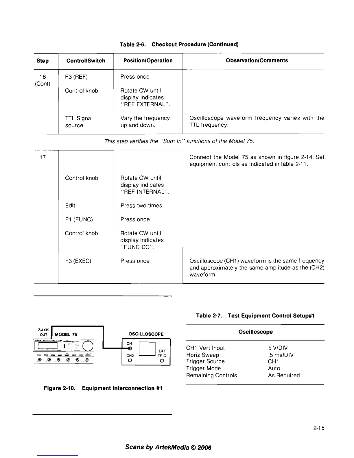
Z-AXIS
OUT
I
MODEL
75
I
OSCILLOSCOPE
Figure 2-10. Equipment Interconnection #1
Table 2-7. Test Equipment Control Setup#l
Oscilloscope
CHI Vert Input
5
VIDIV
Horiz Sweep
.5
mslDlV
Trigger Source
CHI
Trigger Mode Auto
Remaining Controls As Required
Scans
by
ArtekMedia
O
2006