2.2.3 Fuse and Voltage Selection
If
the line voltage is not correct according to table 2-1,
perform the following steps and refer to figure 2-3 for
steps 1 and 2, and figure 2-4 for steps 3 thru 6
tochange
the line voltage and fuse.
1. Remove the two screws holding guard plate to the
rear panel.
2. Remove the guard plate from the rear panel.
GUARD
PLATE
SCREWS
/
VOLTAGE
SELECTOR
CONNECTOR
F
U
AC
PRIMARY
-
VOLTAGE
SELECTOR
Figure 2-3. Guard Plate Removal
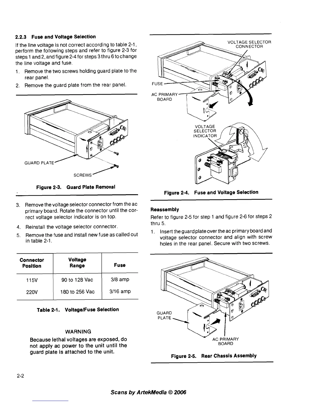
Figure 2-4. Fuse and Voltage Selection
3. Remove the voltage selector connector from the ac
primary board. Rotate the connector until the cor-
rect voltage selector indicator is on top.
4. Reinstall the voltage selector connector.
5. Remove the fuse and install new fuse as called out
in table
2-1.
Connector Voltage
Position Range
90
to 128 Vac 318 amp
Table 2-1. VoltagelFuse Selection
220V
WARNING
Because lethal voltages are exposed, do
not apply ac power to the unit until the
guard plate is attached to the unit.
Reassembly
Refer to figure 2-5 for step 1 and figure 2-6 for steps 2
thru 5.
1. Insert the guard plate over the ac primary board and
voltage selector connector and align with screw
holes in the rear panel. Secure with two screws.
180
to
256 Vac
BOARD
311 6 amp
Figure 2-5. Rear Chassis Assembly
Scans
by
ArtekMedia
63
2006