MODEL
75
OSCILLOSCOPE
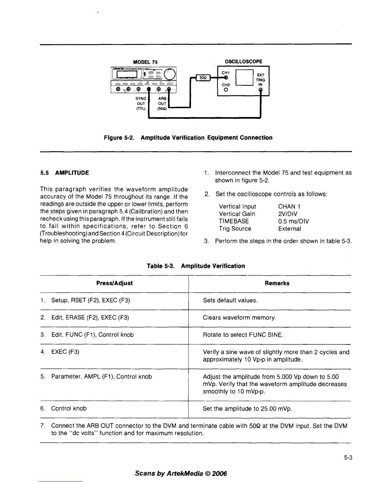
Figure
5-2.
Amplitude Verification Equipment Connection
5.5 AMPLITUDE
This paragraph verifies the waveform amplitude
accuracy of the Model 75 throughout its range. If the
readings are outside the upper or lower limits, perform
the steps given in paragraph 5.4 (Calibration) and then
recheckusing this paragraph. If the instrument still fails
to fall within specifications, refer to Section
6
(Troubleshooting) and Section 4 (Circuit Description)for
help in solving the problem.
1. Interconnect the Model 75 and test equipment as
shown in figure 5-2.
2. Set the oscilloscope controls as follows:
Vertical Input CHAN
1
Vertical Gain 2VlDIV
TIMEBASE 0.5 ms1DIV
Trig Source External
3. Perform the steps in the order shown in table
5-3.
Table
5-3.
Amplitude Verification
PresslAdjust
1. Setup, RSET (F2), EXEC (F3)
4. EXEC (F3)
Remarks
Sets default values.
2. Edit, ERASE
(F2), EXEC (F3)
3. Edit, FUNC
(Fl), Control knob
Verify
a
sine wave of slightly more than 2 cycles and
approximately 10 Vp-p in amplitude.
Clears waveform memory.
Rotate to select FUNC SINE.
5. Parameter, AMPL
(Fl), Control knob
I
Adjust the amplitude from 5.000 Vp down to 5.00
mVp. Verify that the waveform amplitude decreases
smoothly to 10
mVp-p.
7. Connect the ARB OUT connector to the DVM and terminate cable with 50R at the DVM input. Set the DVM
to the "dc volts" function and for maximum resolution.
6.
Control knob
Scans
by
ArtekMedia
O
2006
Set the amplitude to 25.00 mVp.