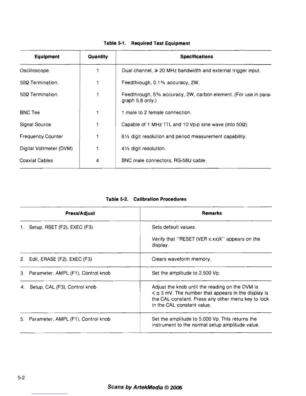
Oscilloscope.
509 Termination.
50R Termination.
Table
5-1.
Required Test Equipment
BNC Tee
Signal Source
Frequency Counter
Digital Voltmeter (DVM)
Coaxial Cables
Equipment
Dual channel,
2
20 MHz bandwidth and external trigger input.
Feedthrough, 0.1
O/O
accuracy, 2W.
Feedthrough,
5% accuracy, 2W, carbon element. (For use in para-
graph 5.8 only.)
Quantity
1 male to 2 female connection.
Specifications
Capable of
1
MHz TTL and 10 Vp-p sine wave (into 50R).
6%
digit resolution and period measurement capability,
4% digit resolution.
BNC male connectors, RG-58U cable.
Table
5-2.
Calibration Procedures
-
-
1
.
Setup, RSET (F2), EXEC (F3)
PresslAdjust
2. Edit, ERASE (F2), EXEC (F3)
c
Remarks
Sets default values.
Verify that "RESET (VER
x.xx)XW appears on the
display.
Clears waveform memory.
3. Parameter, AMPL
(Fl), Control knob
1
Set the amplitude to 2.500 Vp.
--
4. Setup, CAL (F3), Control knob
Adjust the knob until the reading on the DVM is
<
+
3 mV. The number that appears in the display is
the CAL constant. Press any other menu key to lock
in the CAL constant value.
Scans
by
ArtekMedia
O
2006
I
5. Parameter, AMPL (Fl), Control knob
Set the amplitude to 5.000 Vp. This returns the
instrument to the normal setup amplitude value.