U30 PINS
8
&
10
HIGH
-
---------------
--
I
MICROPROCESSOR MODE
CONTROL
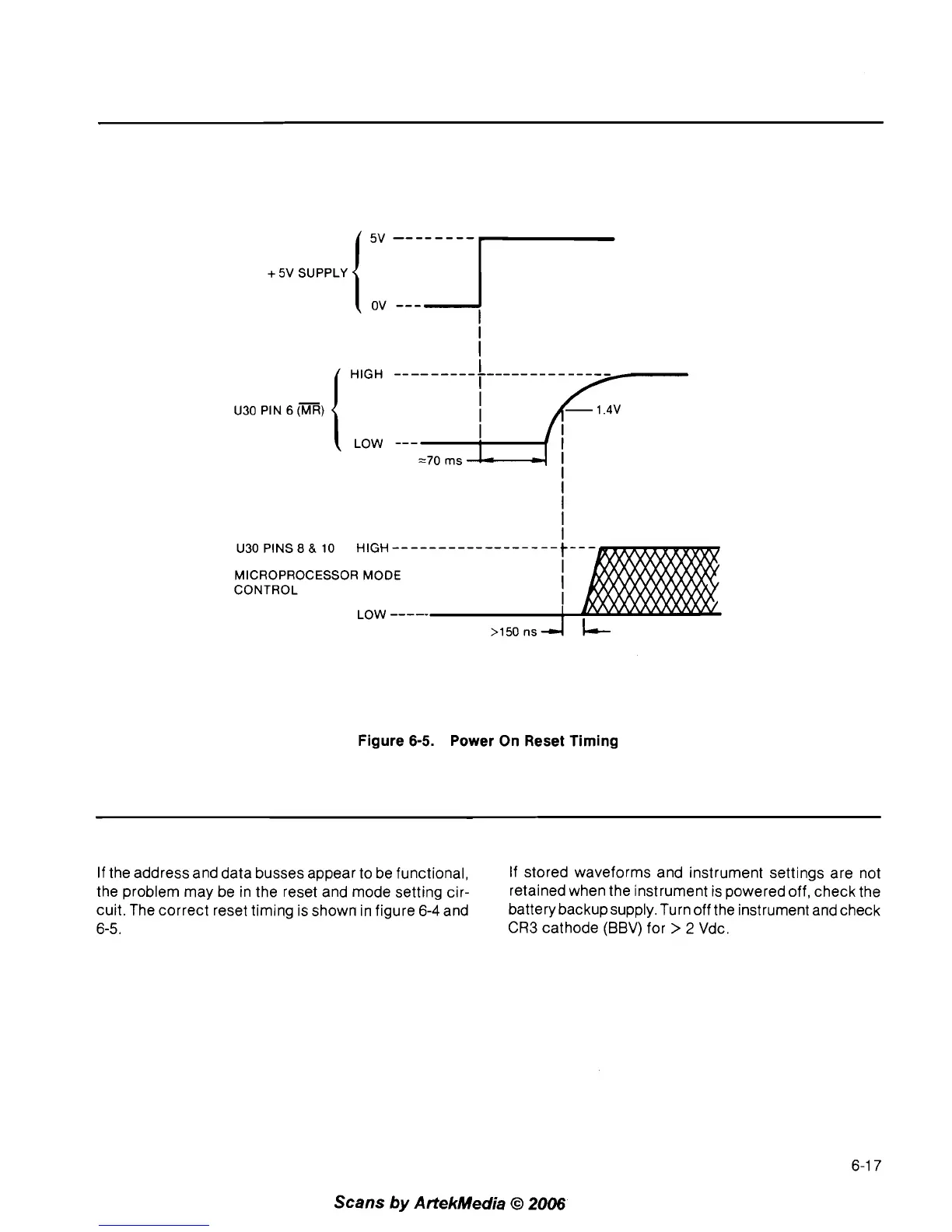
Figure 6-5. Power On Reset Timing
If the address and data busses appear to be functional,
If stored waveforms and instrument settings are not
the problem may be in the reset and mode setting
cir-
retained when the instrument is powered off, check the
cuit. The correct reset timing is shown in figure
6-4
and
batterybackupsupply.Turnoff
the instrument and check
6-5.
CR3
cathode (BBV) for
>
2
Vdc.
Scans
by
ArtekMedia
O
2006