The following is a description of pin functions. Actual
installation is covered in paragraph 2.2.8.
In the DCE configuration, pins 2 and 3 are data input and
output respectively and must be used. Pin 5 may be used
to indicate that the Model 75 is ready to receive data.
Pin 20 tells the Model 75 that the connected device is
ready to receive data, but may be connected to pin 6 of
the Model 75 if the other device is always ready. Pin 7
is signal ground and must be used. Pins 6 and 8 will be
positive (asserted) when the Model 75 is on.
In the DTE configuration, pins 2 and 3 are data output
and input respectively and must be used. Pin 4 will be
positive whenever the Model 75 is On. Pin 5 tells the
Model 75 that the connected device is ready to receive
data.
If
the other device is always ready, pins 4 and 5
of the Model 75 may be connected together. Pins 6 and
8 are properly terminated inputs but have no function.
Pin
20
will be positive when the Model 75 is ready to
receive data. Pin 7 is signal ground and must be used.
1. Determine if the other device is a DCE device or a
DTE device. If this is not explicitly spelled out you
will need to look at the pin out for its connector. If
pin 2 is the data output, the device is a DTE (most
computers). If pin 3 is the data output, the device
is a DCE (most modems). Configure the Model 75
as the opposite type of device by connecting the
internal optioncable to theappropriate
header(see
figure 2-8).
In most cases a straight through cable can be used
to connect the Model 75 with the other device. The
Model 75 only requires the connection of pins 2, 3,
5,7, and 20 but the other device may require more.
Examples of typical cable assemblies are shown in
figure
2-9. However, there are many interpretations
of the
RS-232Cstandard and either of the following
procedures (a or b) should be used to ensure that
the control and handshake signals are properly
connected.
The handshaking method is front panel selectable as
a. If the Model 75 is configured as a DCE then;
CTSIDTR (hardware) or XONIXOFF (see paragraph 3-32
for more information).
(1) Pin 7 (signal ground) is always connected
straight through.
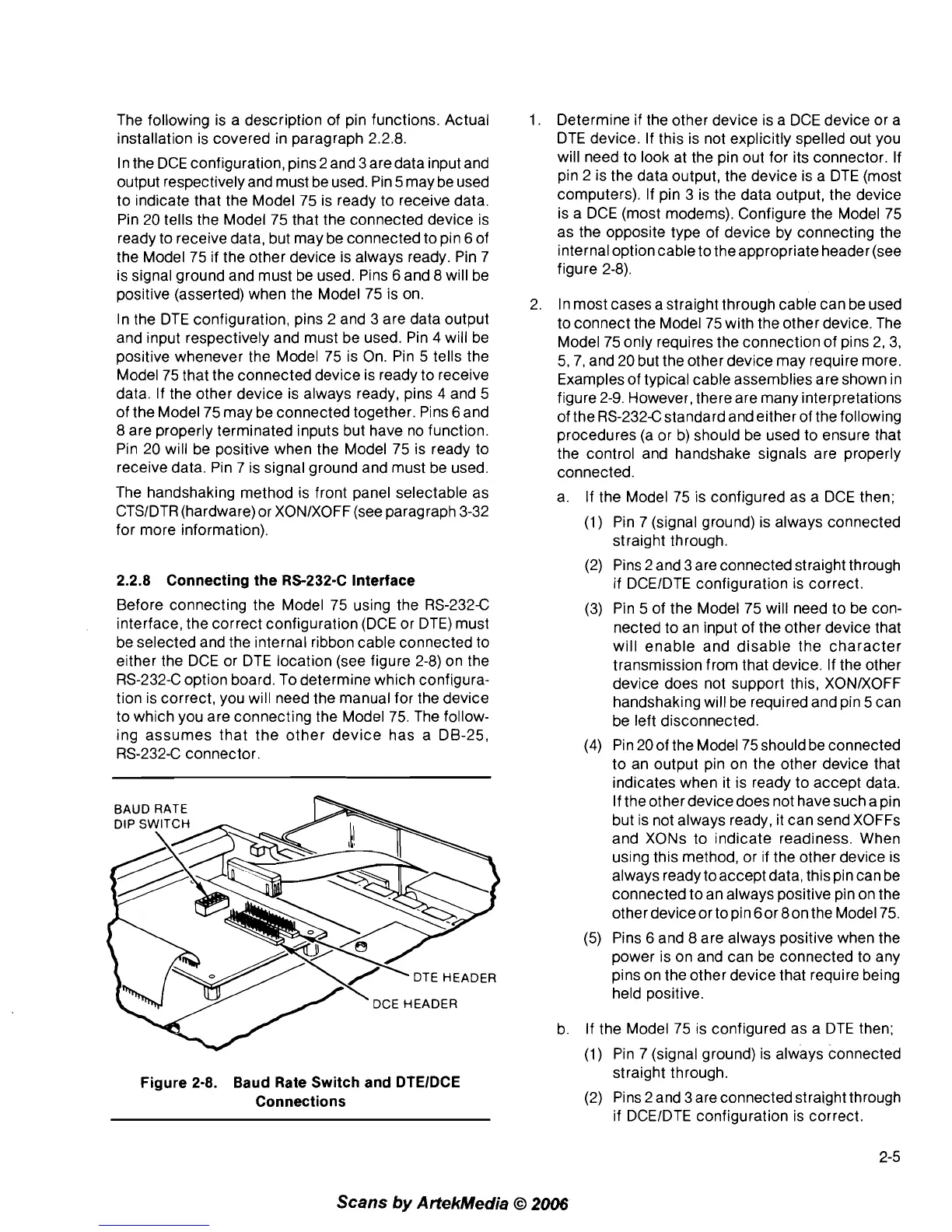
2.2.8 Connecting the RS-232-C Interface
Before connecting the Model 75 using the RS-232C
interface, the correct configuration (DCE or DTE) must
be selected and the internal ribbon cable connected to
either the DCE or DTE location (see figure 2-8) on the
RS-232-C option board. To determine which configura-
tion is correct, you will need the manual for the device
to which you are connecting the Model 75. The follow-
ing assumes that the other device has a DB-25,
RS-232-C connector.
DCE
HEADER
Figure 2-8. Baud Rate Switch and DTElDCE
Connections
(2) Pins
2
and 3 are connected straight through
if
DCEIDTE configuration is correct.
(3) Pin 5 of the Model 75 will need to be con-
nected to an input of the other device that
will enable and disable the character
transmission from that device. If the other
device does not support this, XONIXOFF
handshaking will be required and pin 5 can
be left disconnected.
(4) Pin 20 of the Model 75 should be connected
to an output pin on the other device that
indicates when it is ready to accept data.
If the other device does not have such a pin
but is not always ready, it can send
XOFFs
and XONs to indicate readiness. When
using this method, or if the other device is
always ready
toaccept data, this pin can be
connected to an always positive pin on the
other
deviceor topin 60r 8on the Model 75.
(5) Pins 6 and 8 are always positive when the
power is on and can be connected to any
pins on the other device that require being
held positive.
b. If the Model 75 is configured as a DTE then;
(1) Pin 7 (signal ground) is always connected
straight through.
(2) Pins 2 and 3 are connected straight through
if
DCEIDTE configuration is correct.
Scans
by
ArtekMedia
O
2006