2.2.6 GPlB Address
For Option 001 instruments on the General Purpose
Interface Bus (GPIB), ensure that the instrument GPlB
address is correct. The GPlB default address can be
changed by resetting the internal DIP switch (for access,
remove the top cover, see paragraphs 2.2.2 and 2.2.3)
or changed temporarily by pressing the front panel ADRS
soft key and rotating the Control knob when the GPlB
address is displayed.
The switch sections are labeled from 1 thru 5 and their
OPEN position noted (OPEN
=
Binary "0" in table 2-2).
To verify the address, press ADRS soft key on the front
panel.
Table 2-2. GPlB Address Code
Device
/
Listen
I
Talk
1
1
2
3
4 5
Listen
1
Talk
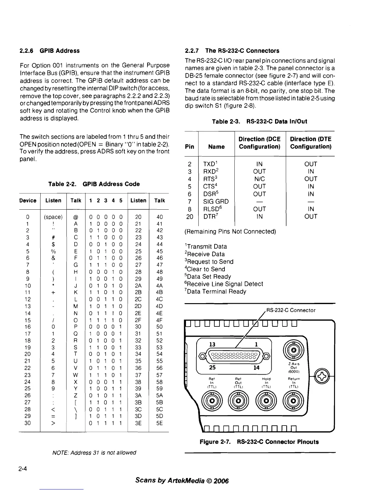
2.2.7 The RS-2324 Connectors
The RS-232C 110 rear panel pin connections and signal
names are given in table
2-3. The panel connector is a
DB-25 female connector (see figure 2-7) and will con-
nect to a standard
RS-232C cable (interface type
E).
The data format is an 8-bit, no parity, one stop bit. The
baud rate is selectable from those listed in table 2-5 using
dip switch
S1 (figure 2-8).
Table 2-3. RS-232-C Data InlOut
40
4
1
42
(Remaining Pins Not Connected)
43
'Transmit Data
'Receive Data
3~equest to Send
4~lear to Send
'Data Set Ready
'Receive Line Signal Detect
7~ata Terminal Ready
Pin
2
3
4
5
6
7
8
20
-
/
RS-232-C Connector
Name
TXD'
RXD~
RTS3
CTS~
DSR5
SIG GRD
RLSD'
DTR~
Direction (DCE
Configuration)
IN
OUT
N IC
OUT
OUT
-
OUT
IN
Z-AXIS
out
I60011
1
Ref Ref
Hold
In
Out
In
In
ITTLI ITTL) lTTLl ITTLI
Direction (DTE
Configuration)
OUT
IN
OUT
IN
IN
-
IN
OUT
nnnnnnnnn
Figure 2-7. RS-232-C Connector Pinouts
NOTE:
Address
31
is
not allowed
Scans
by
ArtekMedia
O
2006