Table 5-3. Amplitude Verification (Cont)
11. Add the magnitudes of both the positive and the negative readings together for the peak to peak amplitude
value and record.
PresslAdjust
8.
Edit, STOP (F2), Control knob
9.
Edit, ADJX,Y (F2), Control knob
10. Control knob
12. Parameter, AMPL
(Fl), Control knob
Remarks
Set the STOP address (SP) to 0000.
Adjust the "Y" value to
"Y
=
2047". Record the
DVM reading.
Adjust the "Y" value to
"Y
=
-
2047". Record the
DVM reading.
Repeat steps
9,
10 and 11 for each of the following
amplitude settings.
Verify that the peak to peak amplitudes are within
the specified limits.
SETTING UPPER LIMIT LOWER LIMIT
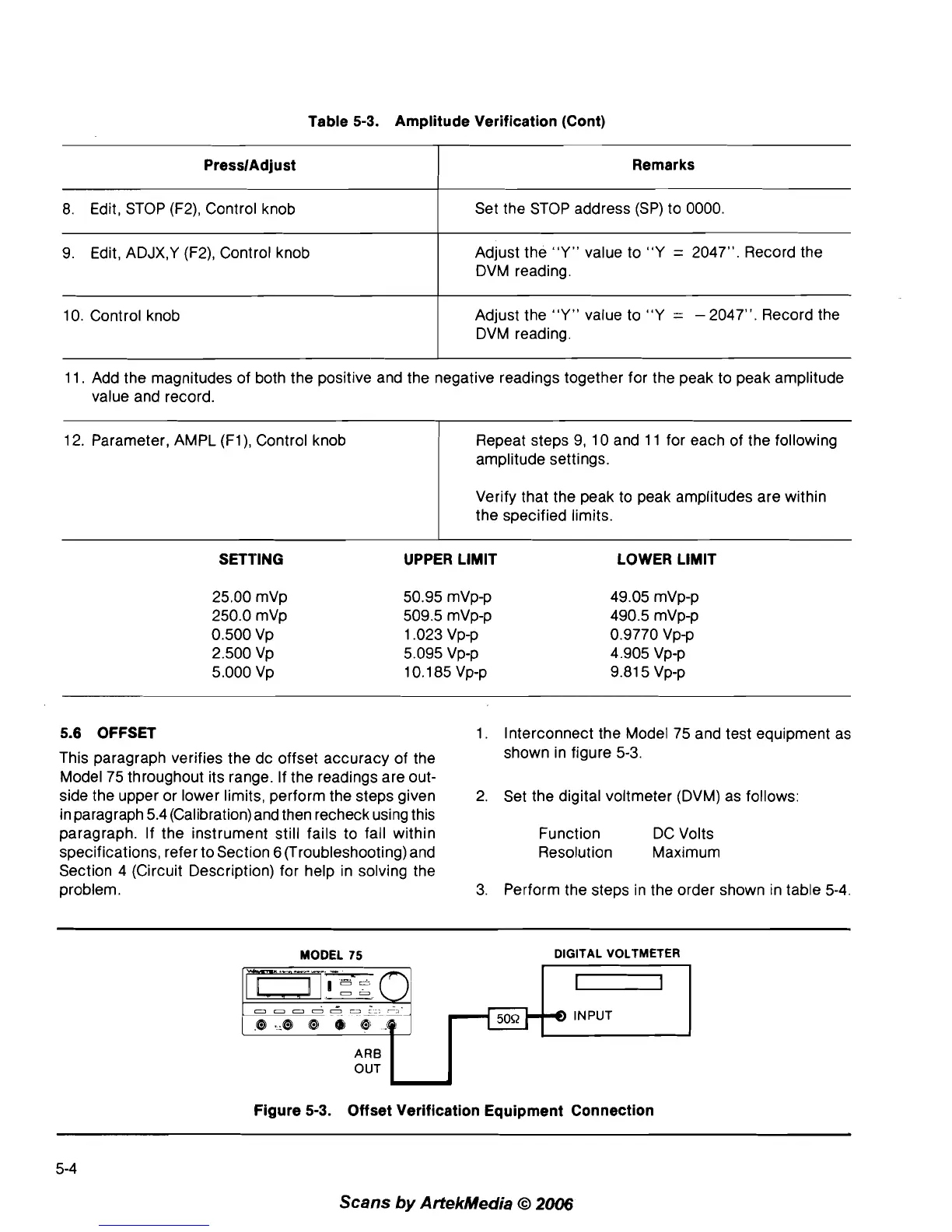
5.6 OFFSET
1. Interconnect the Model 75 and test equipment as
This paragraph verifies the dc offset accuracy of the
shown in figure
5-3.
Model 75 throughout its range. If the readings are out-
side the upper or lower limits, perform the steps given
2.
Set the digital voltmeter (DVM) as follows:
in paragraph 5.4 (Calibration) and then recheck using this
paragraph. If the instrument still fails to fall within
Function DC Volts
specifications, refer to Section
6
(Troubleshooting) and Resolution Maximum
Section 4 (Circuit Description) for help in solving the
problem.
3. Perform the steps in the order shown in table
5-4.
MODEL
75
DIGITAL VOLTMETER
.m!-z
-
0
-
-
ooooo3
->
8 ._8
@
0
@
.@
j
ARB
OUT
L
Figure 5-3. Offset Verification Equipment Connection
Scans
by
ArtekMedia
O
2006