6.2.2 Troubleshooting Dynamic Digital Circuits
Most of thedigital circuits in this instrument aredynamic.
Even with no changes made to the instrument setup,
LOGIC
1
-
-
internal circuits are running and lines are changing
states. This makes troubleshooting difficult without the
-
,
-
--
STATE
use of powerful tools, a logic analyzer for instance.
There is, however, a technique using an oscilloscope
LOGIC 0
-
-
-
-
-
-
- -
-
- -
-
-
-
-
-
-
-
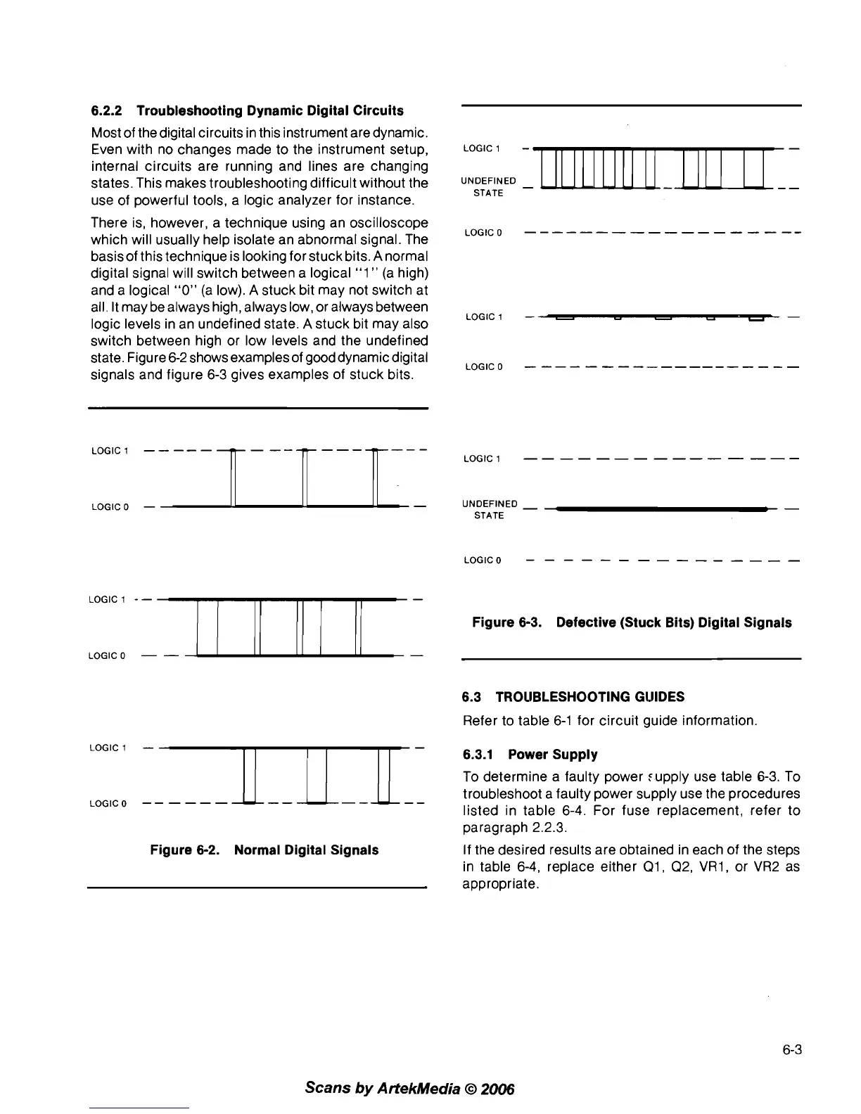
which will usually help isolate an abnormal signal. The
basis of this technique is looking for stuck bits.
A
normal
digital signal will switch between a logical
"1
"
(a high)
and a logical
"0"
(a low).
A
stuck bit may not switch at
all. It may be always high, always low, or always between
LOGIC 1
-
-
-
-
-
-
logic levels in an undefined state.
A
stuck bit may also
switch between high or low levels and the undefined
state. Figure 6-2 shows examples of gooddynamic digital
LOGIC 0
-
-
-
-
-
-
-
-
-
-----
-
-
-
-
-
signals and figure 6-3 gives examples of stuck bits.
LOGIC
1
-
-
-
-
-
-
-
-
-
-
-
-
-
-
-
LOGIC0
-
UNDEFINED
-
-
STATE
LOGIC
1
--
Figure 6-3. Defective (Stuck Bits) Digital Signals
LOGIC0
-
-
6.3 TROllBLESHOOTlNG GI.lIDES
Refer to table 6-1 for circuit guide information.
LOGIC1
-
6.3.1 Power Supply
To determine a faulty power :upply use table
6-3.
To
LOGIC0
--
-
--
-
troubleshoot a faulty power s~pply use the procedures
listed in table
6-4. For fuse replacement, refer to
paragraph
2.2.3.
Figure 6-2. Normal Digital Signals
If the desired results are obtained in each of the steps
in table 6-4, replace either
Q1, Q2, VR1, or VR2 as
appropriate.
Scans
by
ArtekMedia
O
2006