Beforesetting up the instrument, the instrument can be
RECEIVING
MODEL
75
cleared (reset) to the default settings listed in table 3-1
INSTRUMENT
by using the RSET soft key from the Setup menu. RSET
OUTPUT
RG58
OR
EFFECTIVE
will not affect calibration, Z-axis output, or any
IMPEDANCE
EQUIVALENT CIRCUIT
waveforms. To clear the old waveform, in order create
RESISTANCE
~OQ
a new one, the ERASE soft key from the Edit menu can
LOAD
be used. Resetting, then erasing, is normally the best
way to start a new test setup. To use the RSET soft key,
press the Setup key repeatedly until the RSET label is
OUTPUT
AMPLIFIER
seen on the bottom line of the display and then press the
v
RSET soft key (F2) followed by the EXEC soft key (F3).
Table 3-1. Model 75 Default Conditions
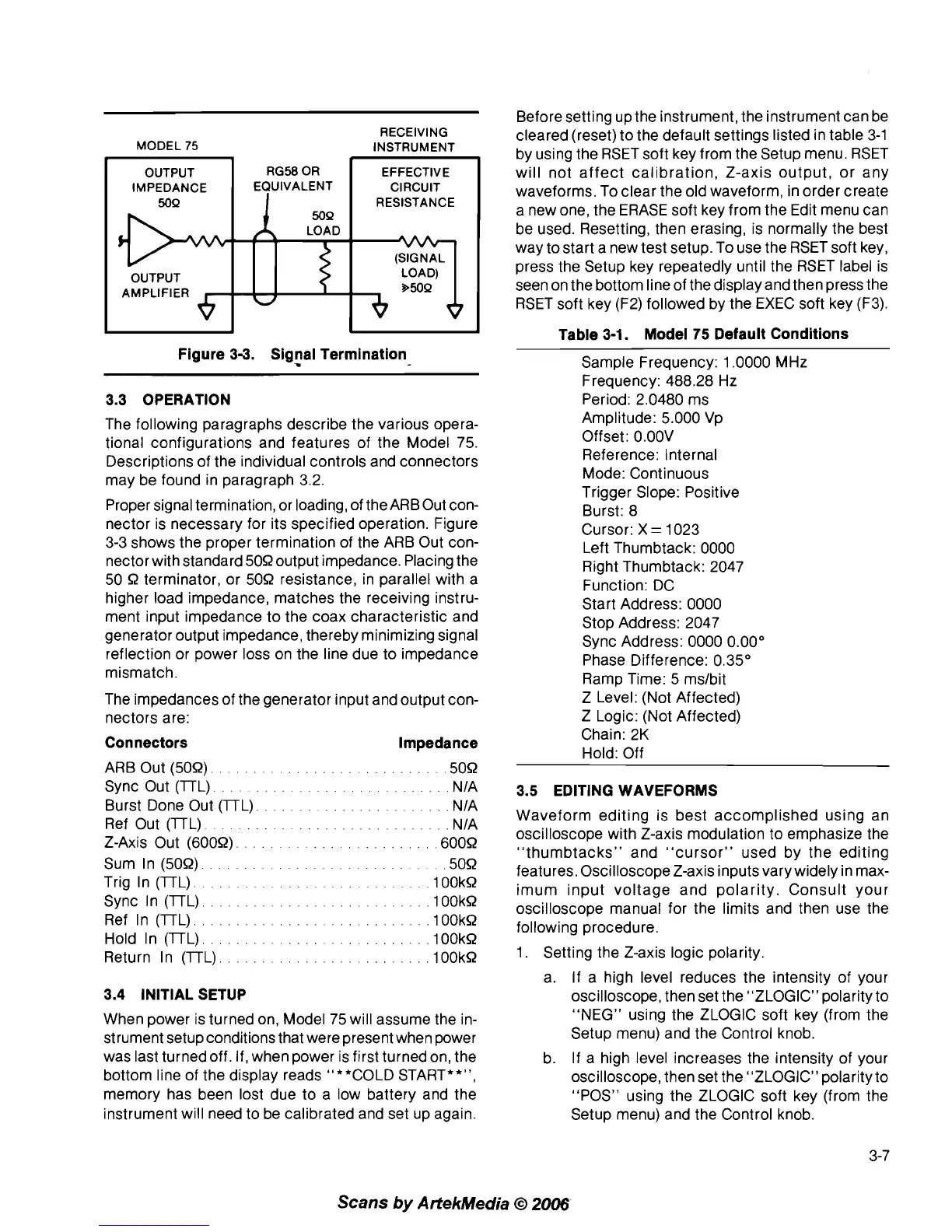
Figure 3-3. Signal Termination
-
3.3 OPERATION
The following paragraphs describe the various opera-
tional configurations and features of the Model 75.
Descriptions of the individual controls and connectors
may be found in paragraph 3.2.
Proper signal termination, or
loadiog, of the ARBOut con-
nector is necessary for its specified operation. Figure
3-3 shows the proper termination of the ARB Out con-
nector with standard 509 output impedance. Placing the
50
9
terminator, or 509 resistance, in parallel with a
higher load impedance, matches the receiving instru-
ment input impedance to the coax characteristic and
generator output impedance, thereby minimizing signal
reflection or power loss on the line due to impedance
mismatch.
The impedances of the generator input and output con-
nectors are:
Connectors Impedance
ARB Out (509).
.........................
,509
Sync Out (lTL).
.........................
NIA
Burst Done Out (lTL).
.....................
NIA
Ref Out (lTL)
......................
NIA
Z-Axis Out (6009).
.................
,6009
Sum In (509).
.........................
,509
Trig In (lTL).
.........................
.1OOkR
Sync In (lTL)
..........................
.100kR
Ref In (lTL)
..........................
.100kR
Hold In (lTL).
.......................
,100kR
Return In (lTL).
.......................
.look9
3.4 INITIAL SETUP
When power is turned on, Model 75 will assume the in-
strument setup conditions that were present when power
was last turned off. If, when power is first turned on, the
bottom line of the display reads "**COLD START**",
memory has been lost due to a low battery and the
instrument will need to be calibrated and set up again.
Sample Frequency: 1.0000 MHz
Frequency: 488.28 Hz
Period: 2.0480 ms
Amplitude: 5.000 Vp
Offset:
O.OOV
Reference: Internal
Mode: Continuous
Trigger Slope: Positive
Burst: 8
Cursor: X
=
1023
Left Thumbtack: 0000
Right Thumbtack: 2047
Function: DC
Start Address: 0000
Stop Address: 2047
Sync Address: 0000 0.00"
Phase Difference: 0.35"
Ramp Time: 5
mslbit
Z Level: (Not Affected)
Z Logic: (Not Affected)
Chain: 2K
Hold: Off
3.5 EDITING WAVEFORMS
Waveform editing is best accomplished using an
oscilloscope with Z-axis modulation to emphasize the
"thumbtacks" and "cursor" used by the editing
features. Oscilloscope Z-axis inputs vary widely in max-
imum input voltage and polarity. Consult your
oscilloscope manual for the limits and then use the
following procedure.
1. Setting the Z-axis logic polarity.
a. If a high level reduces the intensity of your
oscilloscope, then set the "ZLOGIC" polarity to
"NEG"
usiog the ZLOGIC soft key (from the
Setup menu) and the Control knob.
b.
If
a high level increases the intensity of your
oscilloscope, then set the "ZLOGIC" polarity to
"POS" using the ZLOGIC soft key (from the
Setup menu) and the Control knob.
Scans
by
ArtekMedia
O
2006