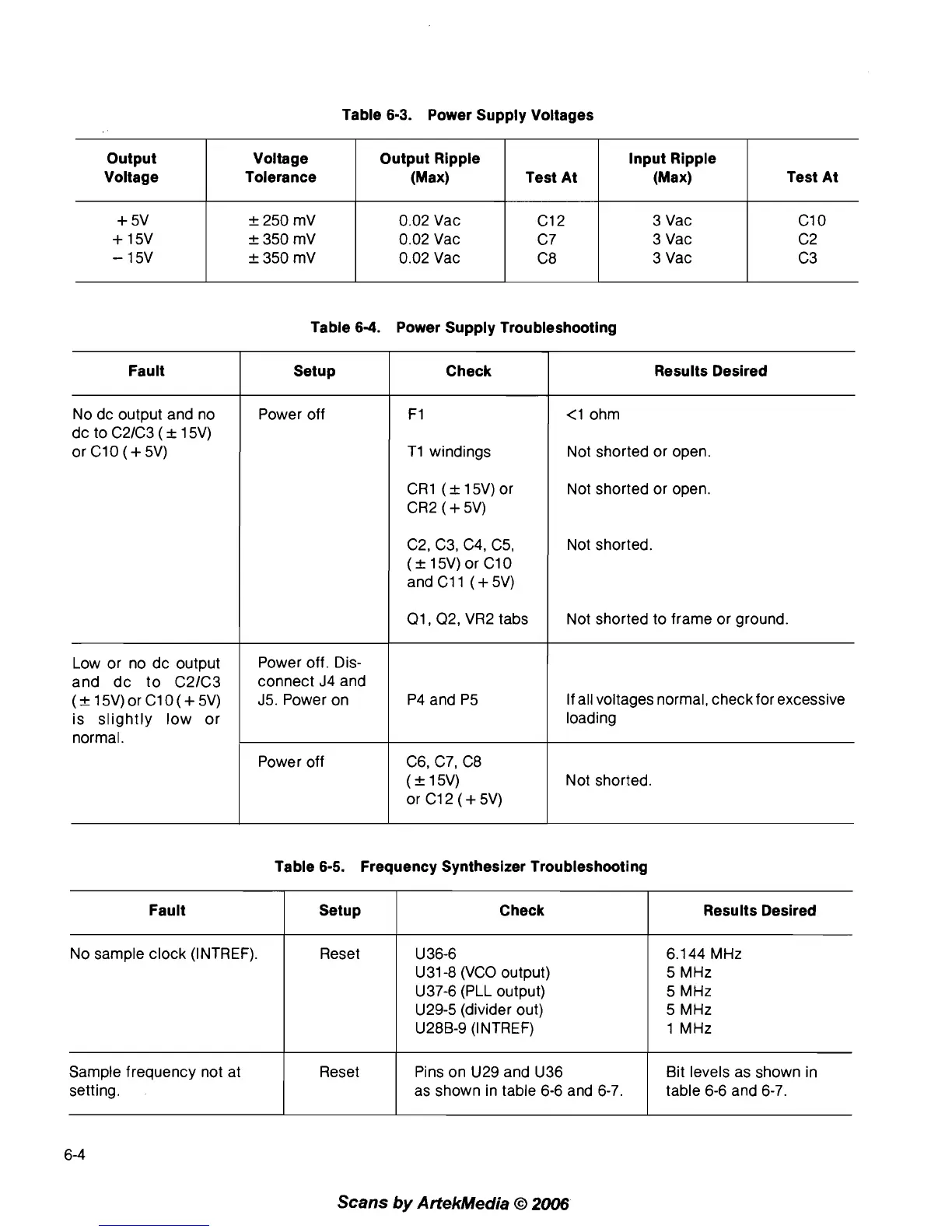
Table
6-3.
Power Supply Voltages
Table
6-4.
Power Supply Troubleshooting
Output
Voltage
+
5V
+
15V
-
15V
Table 6-5. Frequency Synthesizer Troubleshooting
Voltage
Tolerance
k
250 mV
k
350 mV
k
350 mV
Fault
No dc output and no
dc to
C21C3
(
&
15V)
or C10
(+
5V)
Low or no dc output
and dc to
C21C3
(&15V)orC10(+5V)
is slightly low or
normal.
Scans
by
ArtekMedia
O
2006
Output Ripple
(Max)
0.02 Vac
0.02 Vac
0.02 Vac
Setup
Power off
Power off. Dis-
connect J4 and
J5.Poweron
Power off
Fault
No sample clock (INTREF).
Sample frequency not at
setting.
Test At
C12
C7
C8
Check
F1
TI windings
CR1 (+15V)or
CR2
(
+
5V)
C2, C3, C4, C5,
(&
15V) or C10
and C11
(+
5V)
01, 02, VR2 tabs
P4 and P5
C6, C7, C8
(k 15V)
or C12 (+5V)
Setup
Reset
Reset
Results Desired
<1 ohm
Not shorted or open.
Not shorted or open.
Not shorted.
Not shorted to frame or ground.
If all voltages normal, check for excessive
loading
Not shorted.
Input Ripple
(Max)
3 Vac
3 Vac
3 Vac
Check
U 36-6
U31-8 (VCO
output)
U37-6 (PLL output)
U29-5 (divider out)
U28B-9 (INTREF)
Pins on U29 and U36
as shown in table 6-6 and
6-7.
Test At
C10
C2
C3
Results Desired
6.144
MHz
5
MHz
5
MHz
5
MHz
1
MHz
Bit levels as shown in
table 6-6 and 6-7.