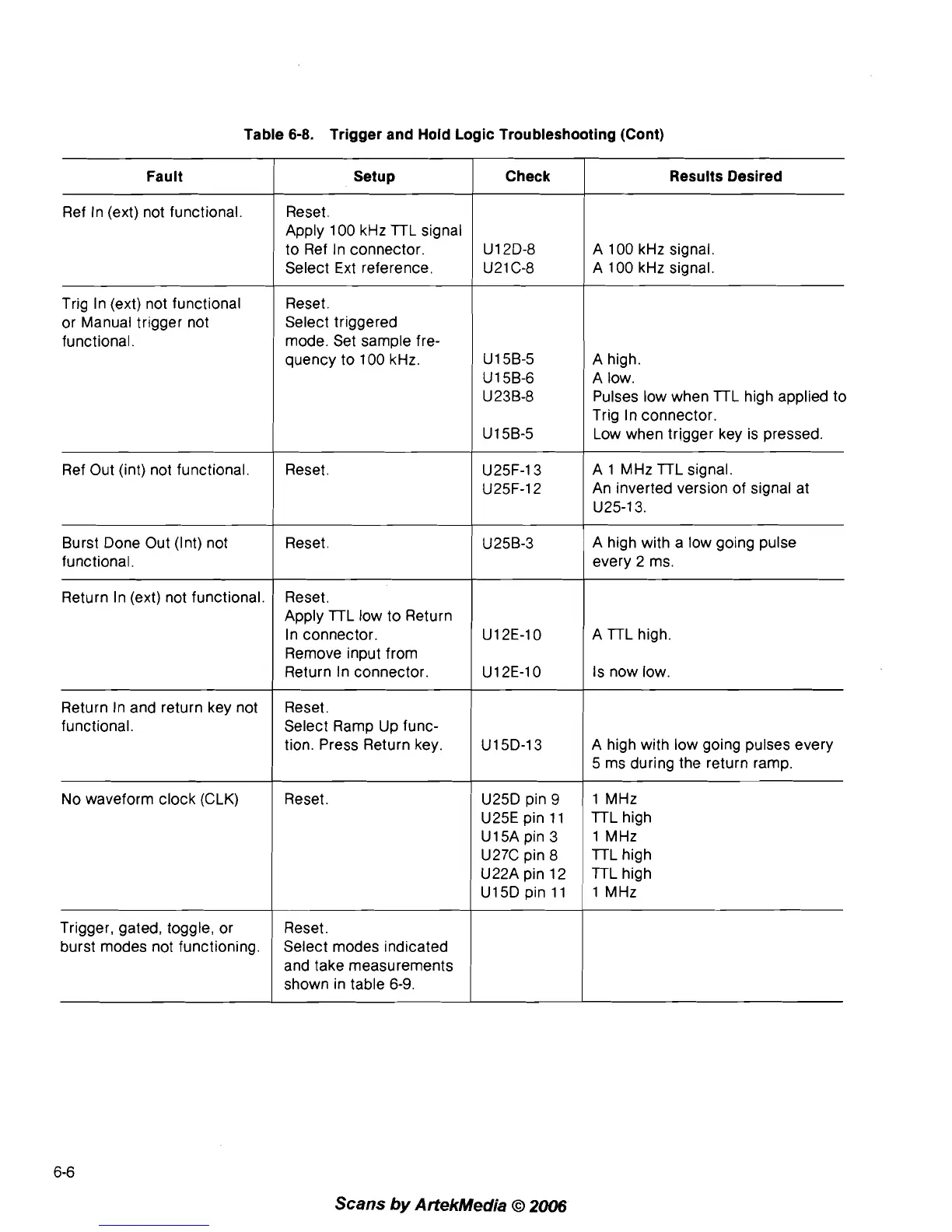
Table 6-8. Trigger and Hold Logic Troubleshooting (Cont)
Fault
Ref In (ext) not functional
Setup
Reset.
Apply 100 kHz
lTL signal
to Ref In connector.
Select Ext reference.
Check Results Desired
A 100 kHz signal.
A 100 kHz signal.
Trig In (ext) not functional
or Manual trigger not
functional.
Reset.
Select triggered
mode. Set sample fre-
quency to 100 kHz.
Ref Out (int) not functional. Reset.
A high.
A low.
Pulses low when
lTL high applied to
Trig In connector.
Low when trigger key is pressed.
A 1 MHz
lTL signal.
An inverted version of signal at
U25-13.
Burst Done Out (Int) not
functional.
Return In (ext) not functional.
Reset.
'
Reset.
Apply
lTL low to Return
In connector.
Remove input from
Return In connector.
A high with a low going pulse
every 2 ms.
A
lTL high.
Is now low.
Return In and return key not
functional.
No waveform clock (CLK)
Trigger, gated, toggle, or
burst modes not functioning.
Reset.
Select Ramp Up func-
tion. Press Return key.
Reset.
Reset.
Select modes indicated
and take measurements
shown in table
6-9.
'
U25D pin 9
U25E pin 11
U15A pin 3
U27C pin
8
U22A pin 12
U15D pin 11
A high with low going pulses every
5 ms during the return ramp.
-
-
1 MHz
lTL high
1 MHz
lTL high
TTL high
1 MHz
Scans
by
ArtekMedia
O
2006