Wecon VD2 SA Series Servo Drives Manual (Lite V1.1)
WECON technology Co., Ltd
Computer sends negative terminal (drive receives negative)
Computer sends positive terminal (drive receives positive)
Computer receives negative terminal (drive sends negative)
Computer receives positive terminal (drive sends positive)
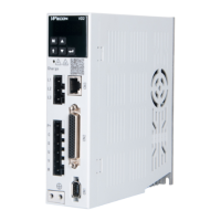
Table 4-20 VD2F pin definitions for CN3 and CN4 interfaces
4.5.2 Communication connection with PLC and other device (RS485)
VD2A and VD2B servo drives communicate with PLC and other devices for Modbus via CN5 or CN6
interface (located on the top of servo drive) by RS485 communication.
Computer sends negative terminal (drive receives negative)
Computer sends positive terminal (drive receives positive)
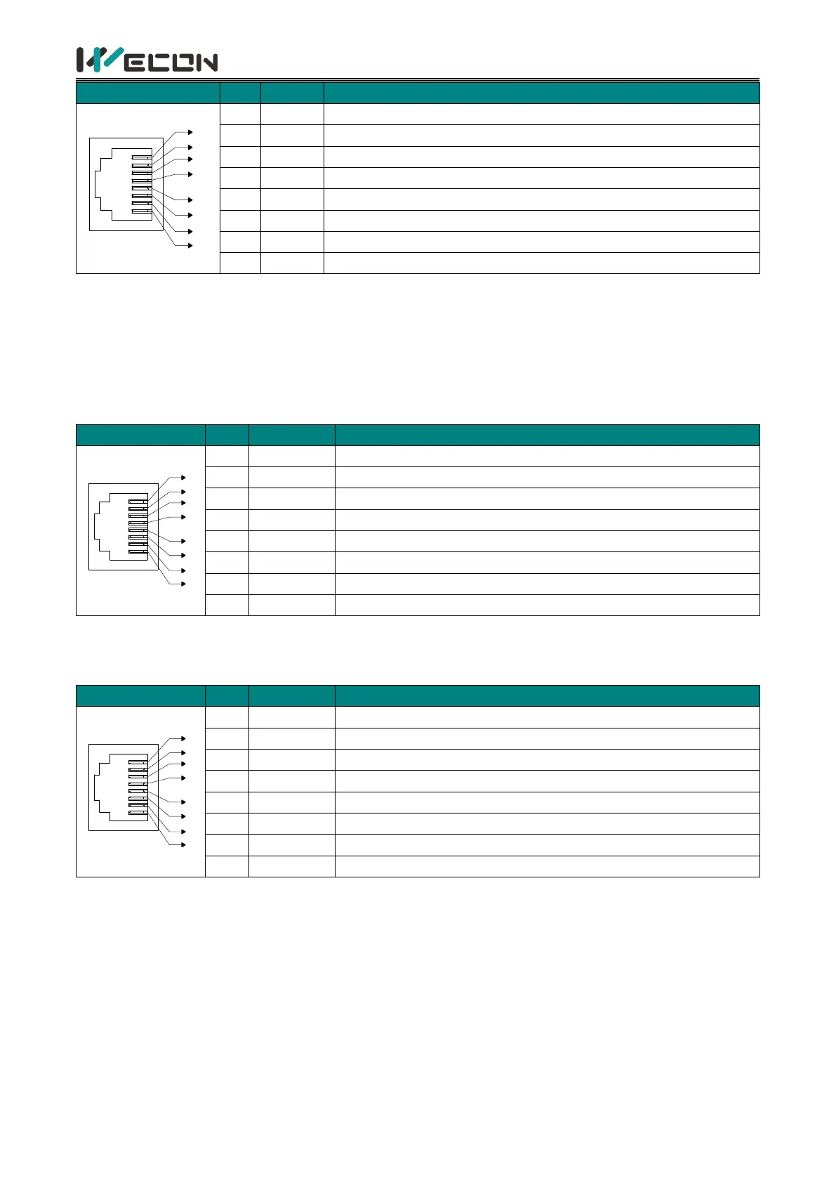
Table 4-21 The pin definition of CN5/CN6 interface
VD2F servo drives communicate with PLC and other devices for Modbus via CN3 or CN4 interface
(located on the top of servo drive) by RS485 communication.
Computer sends negative terminal (drive receives negative)
Computer sends positive terminal (drive receives positive)
Computer receives negative terminal
Computer receives positive terminal
 Loading...