Wecon VD2 SA Series Servo Drives Manual (Lite V1.1)
WECON technology Co., Ltd
5. Panel
5.1 Panel composition
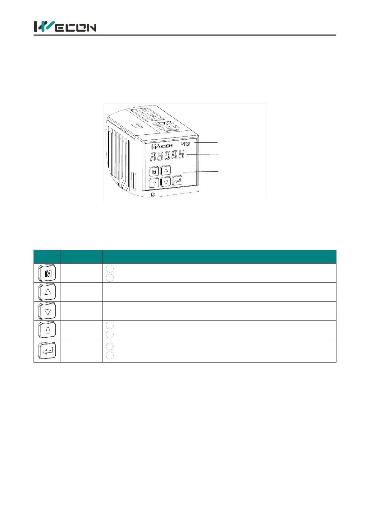
The panel composition of the VD2 series servo drive is shown in Figure 5-1.(take VD2A servo drive
as an example).
LOGO
Panel display
Key function
Figure 5-1 The exterior of VD2 A servo drive panel
The panel of the VD2 series servo drive consists of a display (5-digit LED nixie tube) and keys, which
can be used for the execution of various displays, parameter settings and other functions of the
servo drive. Taking parameter setting as an example, the general functions of the keys are shown in
Table 5-1.
1 Mode switching
2
Return to the previous menu
Increase the value of the LED flashing bit
Decrease the value of the LED flashing bit
1
Change the LED flashing bit
2
View the high-bit value of data with a length greater than 4-bit
1
Enter the next menu
2
Execute commands such as storing parameter setting values
Table 5-1 Key functions
5.2 Panel display
When servo drive is in operation, the panel could be used for status display, parameter display, fault
display and monitoring display of the servo.
Status display: Display the current operating status of servo drive.
Parameter display: Display the function codes corresponding to different functions and the set
values of the function codes.
Fault display: Display the fault code of servo drive.
Monitor display: Display the current operating parameter values of servo drive.
 Loading...