EasyManua.ls Logo

Wecon VD2F-010SA1P - Group P05 Signal Input and Output

Default Icon
133 pages
Print Icon
To Next Page IconTo Next Page
To Previous Page IconTo Previous Page
Loading...
Wecon VD2 SA Series Servo Drives Manual (Lite V1.1)
WECON technology Co., Ltd
70
P04-07
Parameter name
Setting method
Effective time
Default
Range
Category
Unit
1st notch filter
width
Operation
setting
Effective
immediately
4
0 to 12
Vibration
suppression
-
Set the notch filter width grade (the ratio between input and output at the center frequency of the notch filter)
P04-08
Parameter name
Setting method
Effective time
Default
Range
Category
Unit
2nd notch filter
frequency
Operation
setting
Effective
immediately
500
250 to
5000
Vibration
suppression
Hz
Set the center frequency of the 1st notch filter.
When the function code is set to 5000, the function of the notch filter is invalid.
P04-09
Parameter name
Setting method
Effective time
Default
Range
Category
Unit
2nd notch filter
depth
Operation
setting
Effective
immediately
100
0 to 100
Vibration
suppression
-
P04-10
Parameter name
Setting method
Effective time
Default
Range
Category
Unit
2nd notch filter
width
Operation
setting
Effective
immediately
4
0 to 12
Vibration
suppression
-
Group P05 Signal input and output
P05-01
Parameter name
Setting method
Effective time
Default
Range
Category
Unit
AI_1 input bias
Operation
setting
Effective
immediately
0
-5000 to
5000
Analog
input
mV
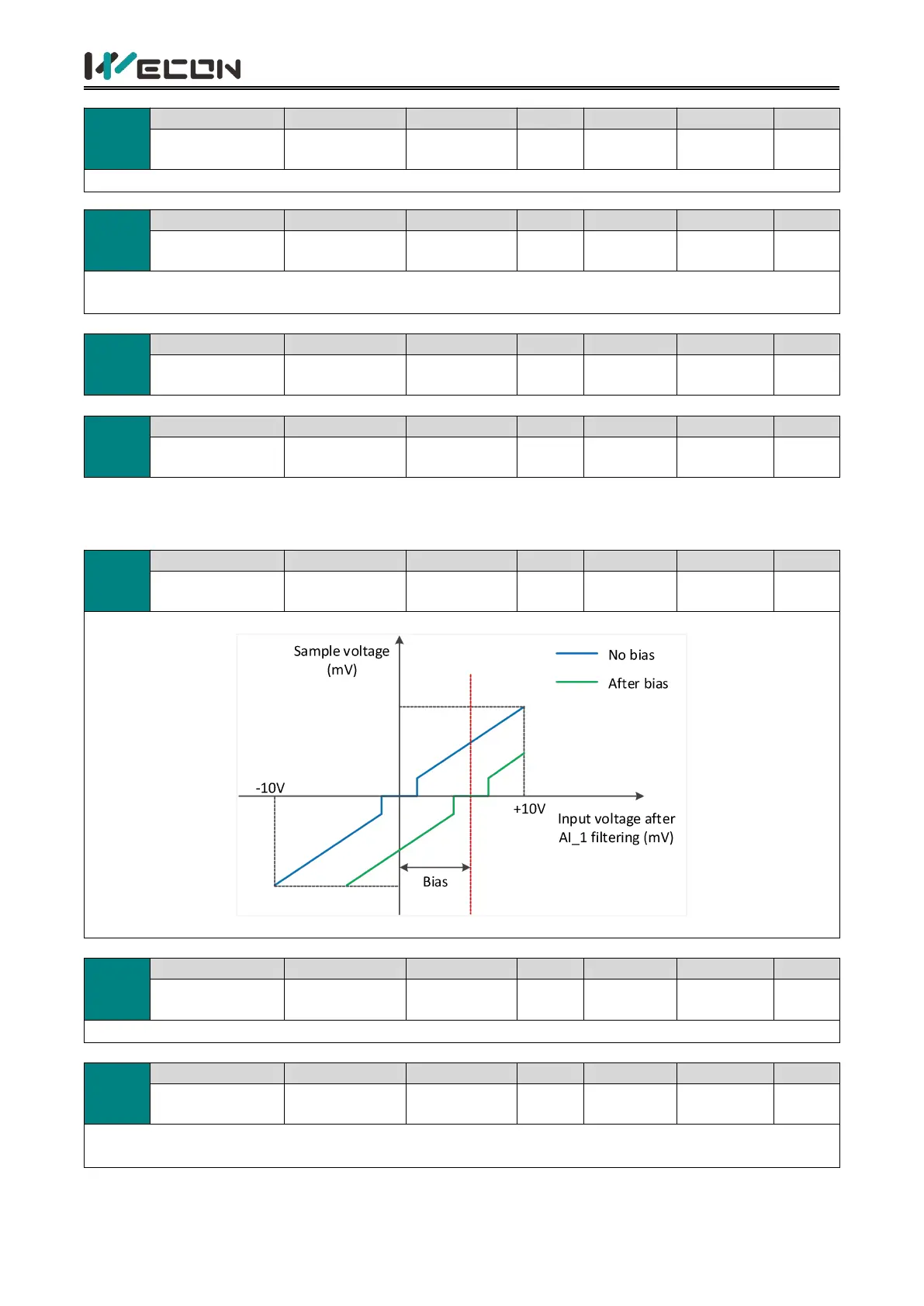
Set AI_1 channel analog bias value.
indicates that the VD2F servo drive does not support this function code.
P05-02
Parameter name
Setting method
Effective time
Default
Range
Category
Unit
AI_1 input filter
time constant
Operation
setting
Effective
immediately
200
0 to 60000
Analog
input
0.01ms
Set AI_1 channel input first-order low-pass filter time constant
P05-03
Parameter name
Setting method
Effective time
Default
Range
Category
Unit
AI_1 dead zone
Operation
setting
Effective
immediately
20
0 to 1000
Analog
input
mV
Set AI_1 channel analog quantity dead zone value. “Dead zone” is the input voltage interval when the sample
voltage is 0.

Table of Contents

Related product manuals