6 | CFW300
English
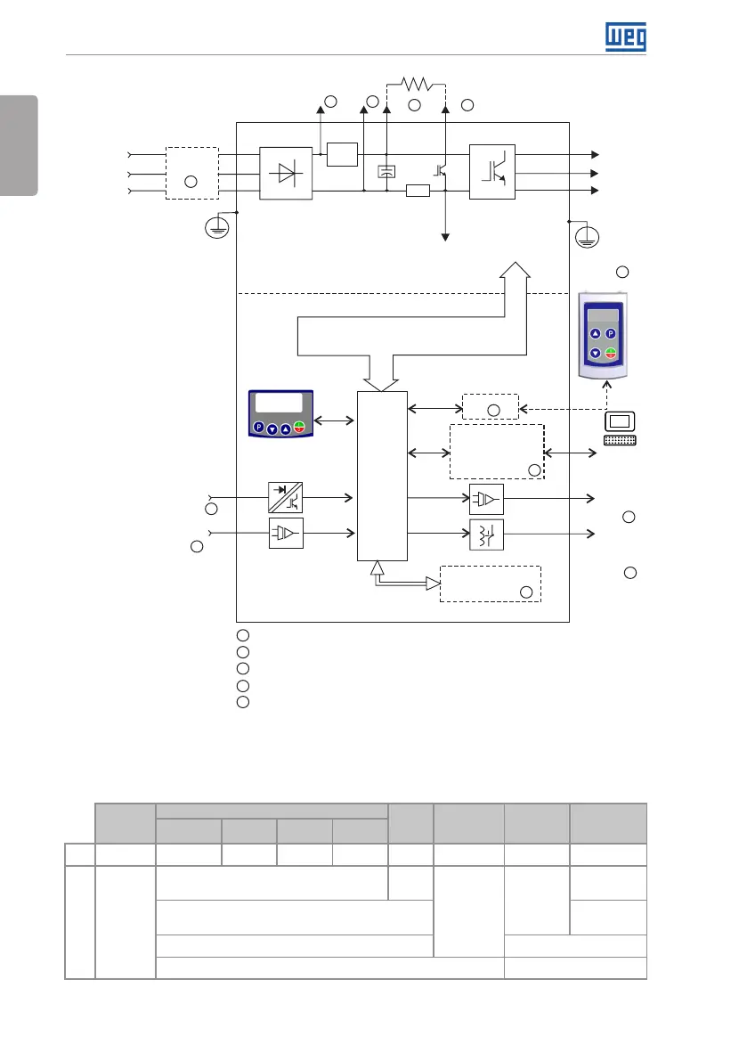
General Information
Braking
IGBT
Digital inputs
(DI1 to DI4)
Sources for electronics and interfaces between
power and control
Power
Three-phase
rectifier
Preload
Motor
3~
U/T1
V/T2
W/T3
Inverter
with IGBT
transistors
Power
supply
R/L1/L
T/L3
RS-485
DC Link
capacitor
bank
HMI
Control
board
with
CPU
16 bits
Flash Memory
Module
Interfaces (RS-232,
RS-485, USB,
CANopen, DeviceNet,
Profibus DP or
Bluetooth)
Analog
output
(AO1)
HMI (remote)
PE
PE
Digital
output
DO1
(RL1)
Software
WPS
Control
Analog input
(AI1)
S/L2/N
Rsh
+UD -UD +BR BR
Filter RFI
5
1 1
4 4
2
2
2
2
3
3
3
3
PC
1
DC power supply connection
2
Available as accessory
3
Number of Inputs/Outputs depends on the I/O expansion accessory used
4
Braking resistor connection
5
Available as accessory only in models single-phase
Figure 2.3: Block diagram of CFW300 for frame size B 220 V
2.3 TERMINOLOGY
Table 2.1: Terminology of the CFW300 inverters
Product
and Series
Model Identification
Brake
Degree of
Protection
Hardware
Version
Software
Version
Frame
Size
Rated
Current
Phase
Number
Rated
Voltage
E.g.: CFW300 A 01P6 S 2 NB 20 --- ---
Available options
CFW300
Refer to Table 2.2 on page 7
Blank =
standard
NB = without braking reostática Sx = special
software
DB = with braking reostática Blank = standard
20 = IP20 Hx = special hardware