10 | CFW300
English
Installation and Connection
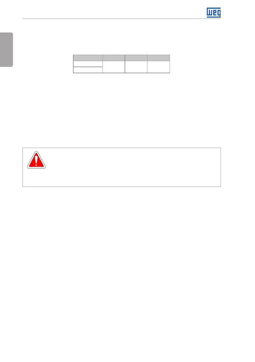
As a reference, Table 3.1 on page 10 shows the air flow of rated ventilation for each model.
Cooling Method: internal fan with air flow upwards.
Table 3.1: Air flow of the internal fan
Model CFM I/s m
3
/min
A
17. 0 8.02 0.48
B
3.1.2.2 Surface Mounting
Figure B2 on page 117 illustrates the CFW300 installation procedure for surface mounting.
3.1.2.3 DIN-Rail Mounting
The CFW300 inverter can also be mounted directly on a 35 mm-rail, in accordance with
DIN EM 50.022. For further details, refer to Figure B2 on page 117.
3.2 ELECTRICAL INSTALLATION
DANGER!
The following information is merely a guide for proper installation. Comply with
applicable local regulations for electrical installations.
Make sure the AC power supply is disconnected before starting the installation.
The CFW300 must not be used as an emergency stop device. Provide other
devices for that purpose.
3.2.1 Identification of the Power Terminals and Grounding Points
The power terminals can be of different sizes and configurations, depending on the model of
the inverter, according to Figure B3 on page 118. The location of the power, grounding and
control connections are shown in Figure B3 on page 118.
Description of the power terminals:
L/L1, N/L2, L3 (R,S,T): power supply connection.
U, V and W: connection for the motor.
-UD: negative pole of the DC power supply.
+UD: positive pole of the DC power supply.
+BR, BR: connection of the braking resistor (available for frame size B models).
PE: grounding connection.
The maximum tightening torque of the power terminals and grounding points must be checked
in Figure B3 on page 118.