CFW300 | 15
English
Installation and Connection
3.2.3.3 Dynamic Braking
NOTE!
The dynamic braking is available from frame size B.
Refer to Table B1 on page 113 for the following specifications of the dynamic braking: maximum
current, resistance, effective current (*) and cable gauge.
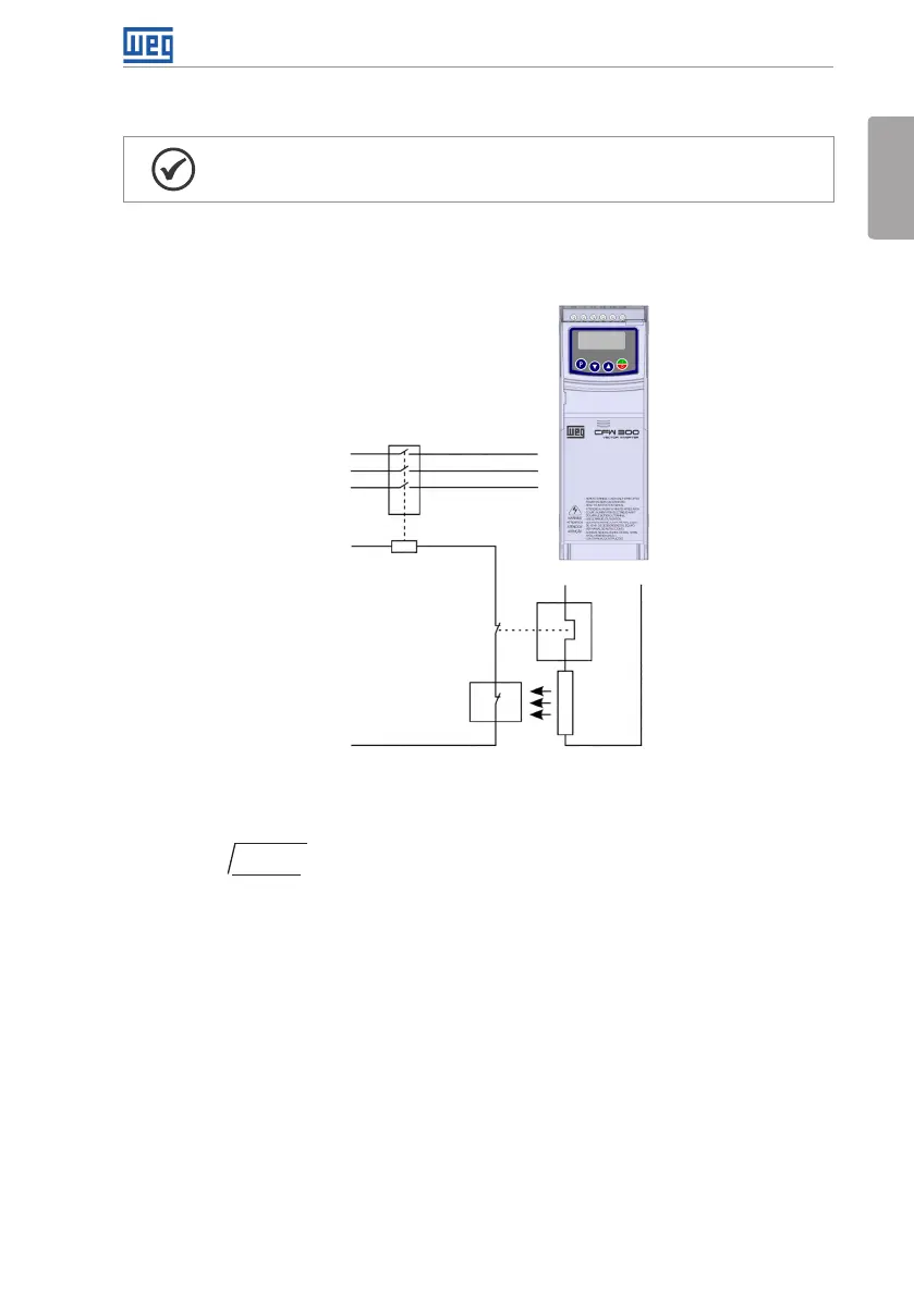
Input power
supply
Thermostat
Brake
resistor
Relay
Command
power supply
Contactor
R
S
T
BR+BR
Figure 3.2: Installation of brake resistor
(*) The effective braking current can be calculated as follows:
I
effective
= I
max
.
t
br
(min)
√
5
Seeing that: t
br
corresponds to the sum of the braking actuation times during the most severe
cycle of five minutes.
The power of the brake resistor must be calculated considering the deceleration time, the inertia
of the load and of the resistive torque.
Procedure to use the dynamic braking:
Connect the brake resistor between the power terminals +BR and BR.
Use a twisted cable for the connection. Separate these cables from the signal and control
wiring.
Dimension the cables according to the application, observing the maximum and effective
currents.