CFW300 | 17
English
Installation and Connection
3.2.4 Grounding Connections
DANGER!
The inverter must be connected to a protective ground (PE).
Use a minimum wire gauge for ground connection equal to the indicated in
Table B1 on page 113.
Connect the inverter grounding connections to a ground bus bar, to a single
ground point or to a common grounding point (impedance ≤ 10 Ω).
The neuter conductor of the line that feeds the inverter must be solidly
grounded; however, this conductor must not be used to ground the inverter.
Do not share the grounding wiring with other equipment that operate with high
currents (e.g.: high voltage motors, welding machines, etc.).
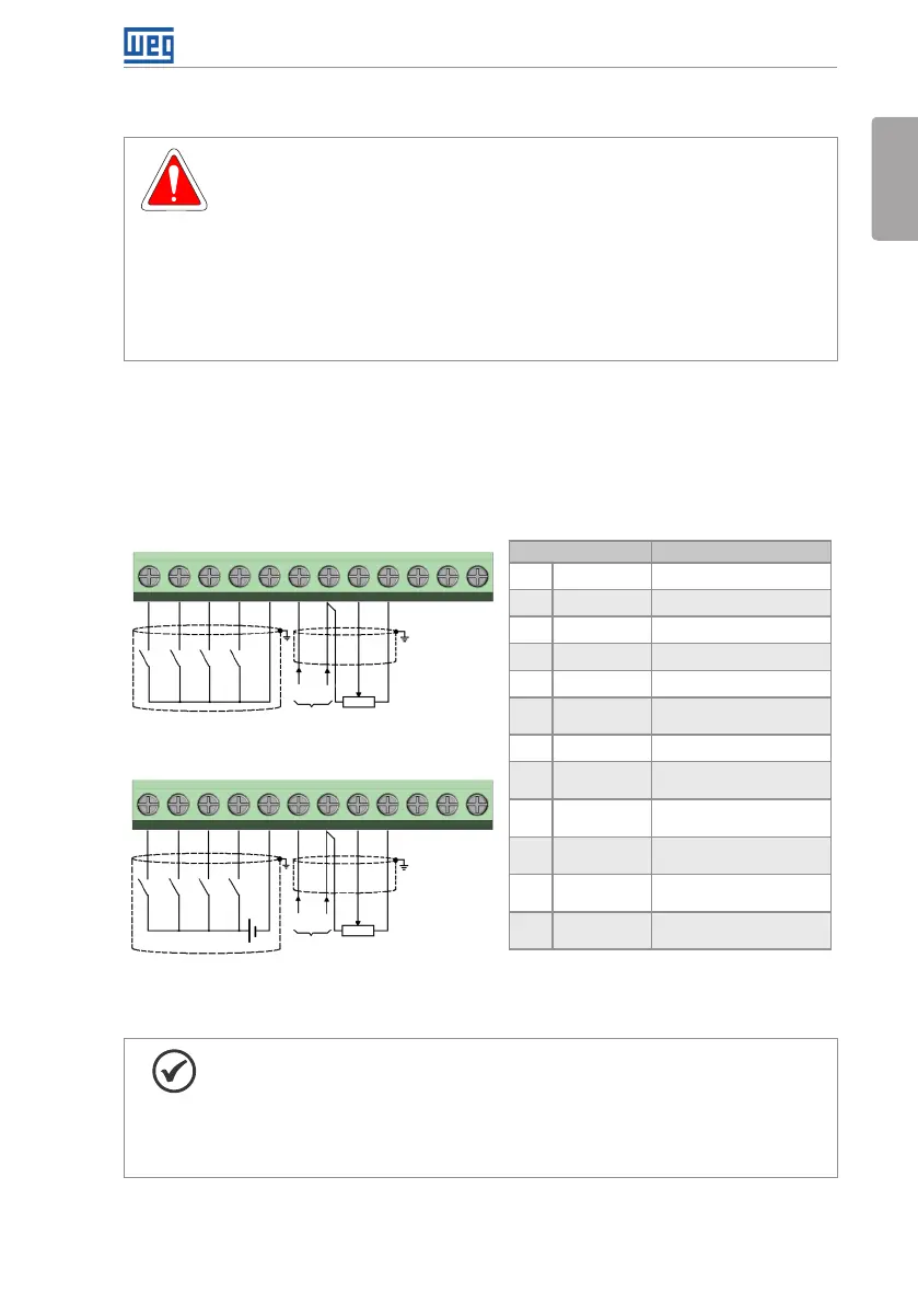
3.2.5 Control Connections
The control connections must be made in accordance with the specification of the connector
of the CFW300 control board. Functions and typical connections are presented in Figure 3.3 on
page 17. For further details on the specifications of the connector signals, refer to Chapter
8 TECHNICAL SPECIFICATIONS on page 31.
(a) NPN Configuration
(b) PNP Configuration
DI1DI1
DI2DI2
DI3DI3
DI4DI4
+10 V+10 V
GNDGND
GNDGND
1
1
10
10
11
11
12
12
2
2
3
3
4
4
5
5
6
6
7
7
8
8
9
9
(+) AI1 (-)
(+) AI1 (-)
(0 a 20) mA
(0 a 20) mA
(4 a 20) mA
(4 a 20) mA
(0 a 10) V
(0 a 10) V
AI1
AI1
24 V
(External supply)
DO1-RL-NCDO1-RL-NC
DO1-RL-NODO1-RL-NO
DO1-RL-CDO1-RL-C
(*) For further information, refer to the detailed specification in
Section 8.2 ELECTRONICS/GENERAL DATA on page 32.
Connector Description
(*)
1 DI1 Digital input 1
2 DI2 Digital input 2
3 DI3 Digital input 3
4 DI4 Digital input 4
5 GND Reference 0 V
6 AI1 Analog input 1
(Current)
7 GND Reference 0 V
8 AI1 Analog input 1
(Tension)
9 +10 V Reference +10 Vdc
for potentiometer
10 DO1-RL-NC Digital output 1
(NC contact of relay 1)
11 DO1-RL-C Digital output 1
(Common point of relay 1)
12 DO1-RL-NO Digital output 1
(NO contact of relay 1)
Counter
clockwise
Counter
clockwise
Clockwise Clockwise
Figure 3.3: (a) and (b) Signals of C300 control card connector
NOTE!
The CFW300 inverters are supplied with the digital inputs configures as active
low (NPN). In order to change the configuration, check the use of parameter
P271 in the programming manual of the CFW300.
Analog input AI1 is set for input 0 to 10 V, in order to change, check parameter
P233 of the programming manual.