4 | CFW300
English
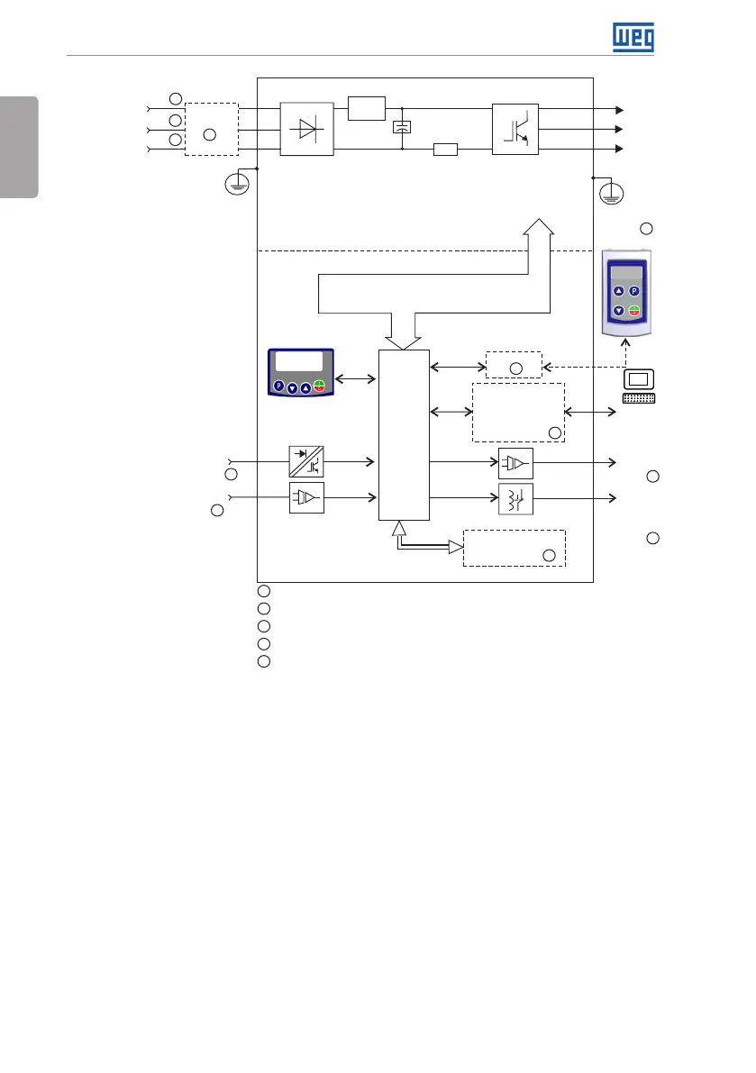
General Information
Digital inputs
(DI1 to DI4)
Sources for electronics and interfaces between
power and control
Power
Single-phase /
three-phase
rectifier
Preload
Motor
3~
U/T1
V/T2
W/T3
Inverter
with IGBT
transistors
Power
supply
R/L1/L (-UD)
T/L3
RS-485
DC Link
capacitor
bank
HMI
Control
board
with
CPU
16 bits
Flash Memory
Module
Interfaces (RS-232,
RS-485, USB,
CANopen, DeviceNet,
Profibus DP or
Bluetooth)
Analog
output
(AO1)
HMI (remote)
PE
PE
Digital
output
DO1
(RL1)
Software
WPS
Control
PC
Analog input
(AI1)
S/L2/N (+UD)
Rsh
Filter RFI
1
1
2
5
3
3
3
3
4
4
4
4
1
DC power supply connection available for specific models only
2
Three-phase power supply connection available for specific models only
3
Available as accessory
4
Number of Inputs/Outputs depends on the I/O expansion accessory used
5
Available as accessory only in models single-phase
Figure 2.1: Block diagram of CFW300 for frame size A 220 V