1
/
4
-DIN,
1
/
8
-DIN &
1
/
16
- DIN Controllers & Indicators - Product Manual
59305, Issue 5 – March 2005 Modbus Communications Page 95
Device Addressing
The instrument is assigned a unique device address by the user in the range 1 (default) to
255 using the 5DD9 parameter in Configuration Mode. This address is used to recognise
Modbus Queries intended for this instrument. The instrument does not respond to Modbus
Queries that do not match the address that has been assigned to it.
The instrument will also accept global Queries using device address 0 no matter what device
address is assigned. No responses are returned for globally addressed Queries.
Supported Modbus Functions
Modbus defines several function types; these instruments support the following types:
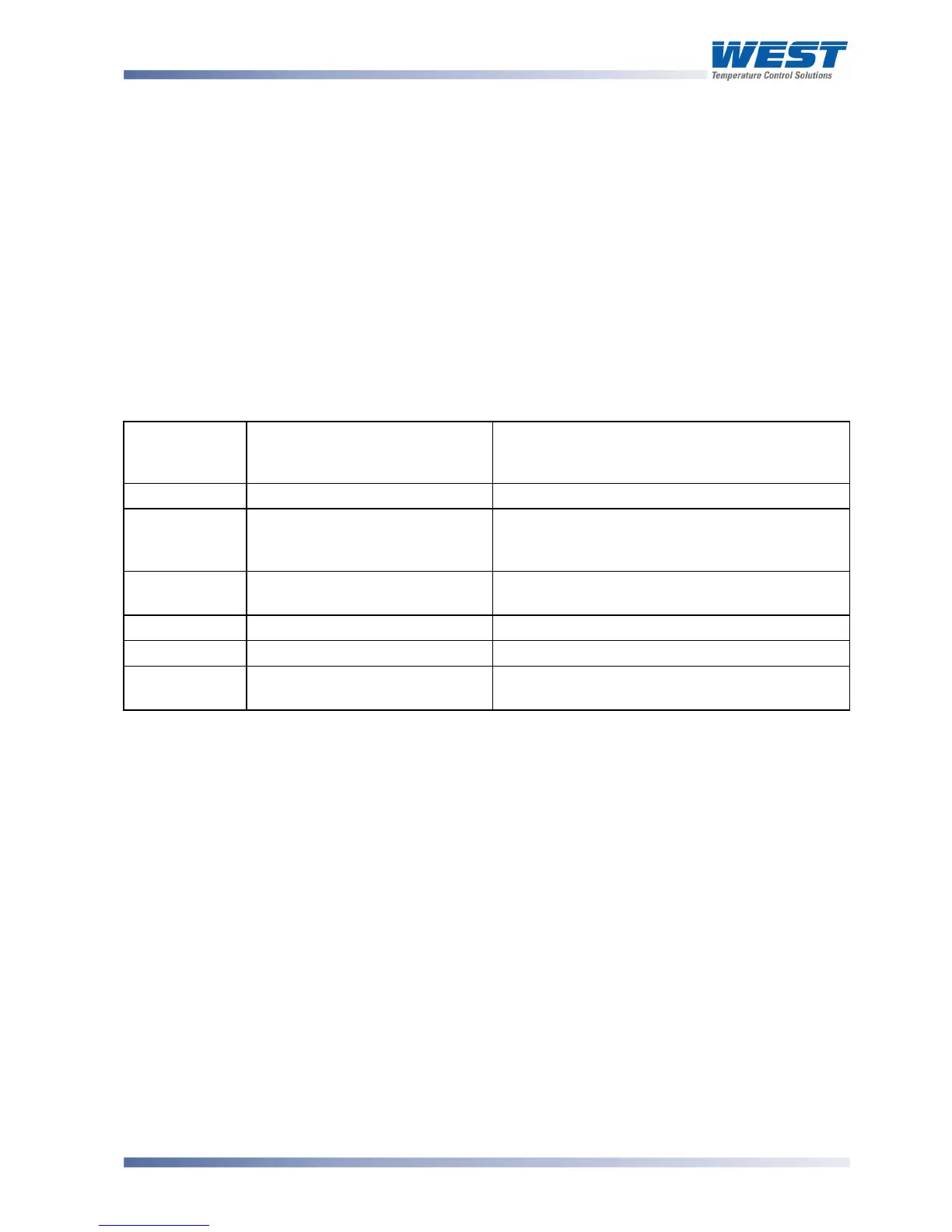
Table 26. Supported Modbus Functions
Function
Code
(decimal)
Modbus Meaning Description
01 / 02 Read Coil/Input Status Read output/input status bits at given address.
03 / 04 Read Holding/Input registers Read current binary value of specified number
of parameters at given address. Up to 64
parameters can be accessed with one Query.
05 Force single Coil Writes a single binary bit to the Specified Slave
Bit address.
06 Pre-set Single Register Writes two bytes to a specified word address.
08 Diagnostics Used for loopback test.
16 Pre-set Multiple Registers Writes up to 1 word parameter values to the
specified address range.
Function Descriptions
The following is interpreted from the Modbus Protocol Description obtainable from
http://www.modicon.com/ or http://www.modbus.org/. Refer to that document if clarification is
required.
In the function descriptions below, the preceding device address value is assumed, as is the
correctly formed two-byte CRC value at the end of the QUERY and RESPONSE frames.