1
/
4
-DIN,
1
/
8
-DIN &
1
/
16
- DIN Controllers & Indicators - Product Manual
Page 64 P6700, P8700& P4700 Model Group 59305, Issue 5 – March 2005
P6700, P8700 & P4700 Limit Controllers - Operator Mode
This is the mode used during normal operation of the instrument. It can be accessed from
Select Mode, and is the usual mode entered at power-up.
WARNING:
IN NORMAL OPERATION, THE OPERATOR MUST NOT REMOVE THE INSTRUMENT FROM
ITS HOUSING OR HAVE UNRESTRICTED ACCESS TO THE REAR TERMINALS, AS THIS
WOULD PROVIDE POTENTIAL CONTACT WITH HAZARDOUS LIVE PARTS.
CAUTION:
Set all Configuration Mode parameters and Setup Mode parameters as required
before starting normal operations.
Navigating in Operator Mode
Press to move between displays.
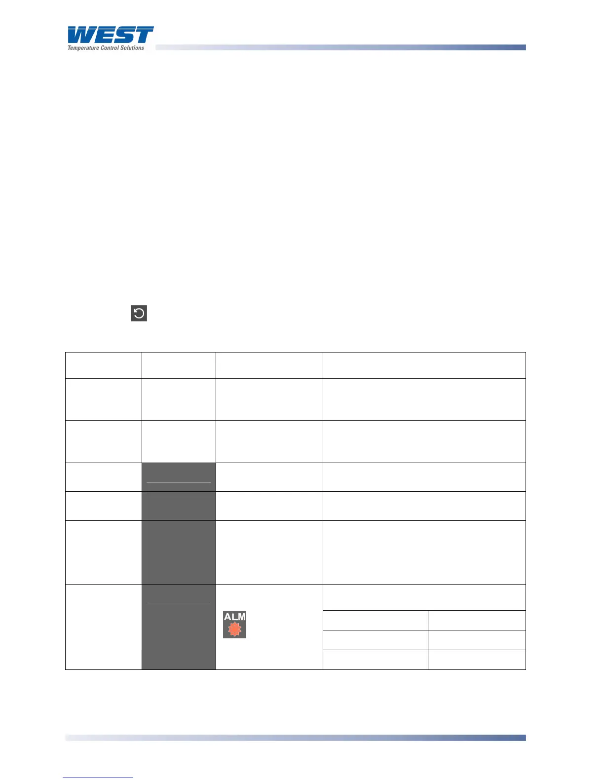
Table 18. P6700, P8700 & P4700 Operator Mode Displays
Upper
Display
Lower
Display
When Visible Description
PV Value
Limit SP
Value
Display strategy is
set to
.%56.
(Initial Screen)
Process Variable and Limit Setpoint
values.
Read only
Limit SP
Value
Blank
Display strategy is
set to
D<:5.
(Initial Screen)
Limit Setpoint value only.
Read only
High Limit
Hold
)<)D'
$#9+
= )< in
Configuration Mode
Highest PV value since this parameter
was last reset.
Low Limit
Hold
+")D'
$#9+
= +" in
Configuration Mode
Lowest PV value since this parameter was
last reset.
Exceed Time
Value
#<'
Always available Accumulated time of Limit SP exceed
conditions since this parameter was last
reset. Time Format: mm.ss to 99.59, then
mmm.s (10 sec increments)
Shows
())* when ≥999.9
Upper display shows which alarm(s) are
active. Inactive alarms are blank
'''2'
Alarm 1 Active
''3'
Alarm 2 Active
Active Alarm
Status
5+:#'
When any alarm is
active.
ALM indicator
will also flash
5%'
Annunciator Active
Limit Setpoint Adjustment
Adjustment of the Limit Setpoint can be only made from Setup Mode.