1
/
4
-DIN,
1
/
8
-DIN &
1
/
16
- DIN Controllers & Indicators - Product Manual
Page 26 Connections 59305, Issue 5 – March 2005
11
12
RS485
16
17
18
COM
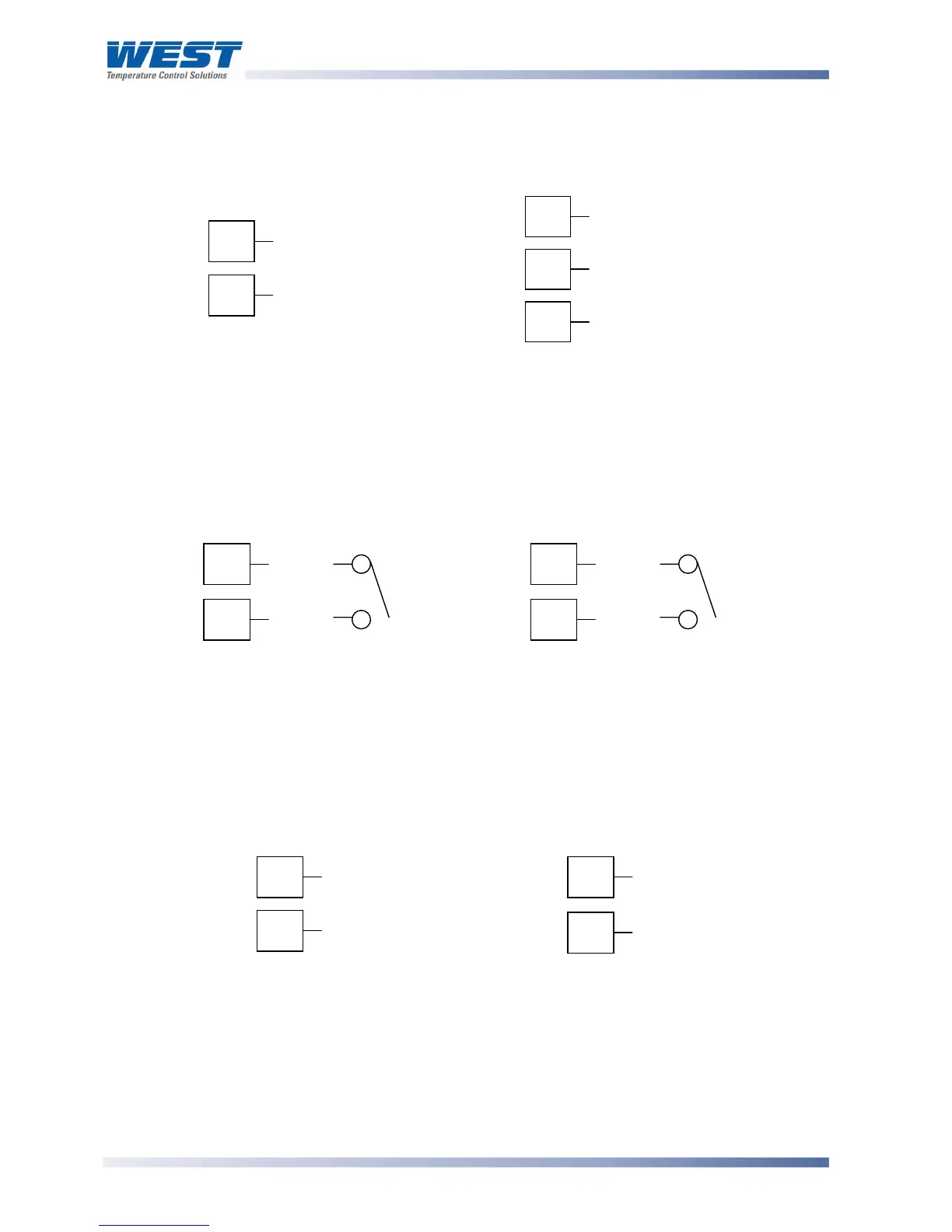
Option Slot A Connections - RS485 Serial Communications Module
If option slot A is fitted with the RS485 serial communication module, connections are as
illustrated. Carefully observe the polarity of the A (Rx/Tx +ve) and B (Rx/Tx -ve) connections.
1
/
16
DIN
1
/
4
DIN &
1
/
8
DIN
Figure 32. Option Slot A – RS485 Serial Communications Module
Option Slot A Connections - Digital Input Module
If a digital input module is fitted in option slot A, this may be connected to either voltage free
contacts (e.g. switch or relay), or a TTL compatible voltage. Connections are shown below.
1
/
16
DIN
1
/
4
DIN &
1
/
8
DIN
Figure 33. Option Slot A – Digital Input Module
Option Slot A Connections – Basic RSP
If option slot A is fitted with a basic remote setpoint module, input connections are as shown.
For
1
/
4
-DIN &
1
/
8
-DIN models it is recommend that the full RSP (Option Slot B) is used
instead, as this has additional features and leaves option slot A free for other modules.
1
/
16
DIN
1
/
4
DIN &
1
/
8
DIN
Figure 34. Option Slot A – Basic RSP Input Module
WARNING:
THIS MODULE MUST NOT BE FITTED IF FULL RSP HAS BEEN FITTED IN OPTION SLOT B.
16
17
_
+
11
12
+
_
16
17
_
+
11
12
+
_