1
/
4
-DIN,
1
/
8
-DIN &
1
/
16
- DIN Controllers & Indicators - Product Manual
59305, Issue 5 – March 2005 Connections Page 17
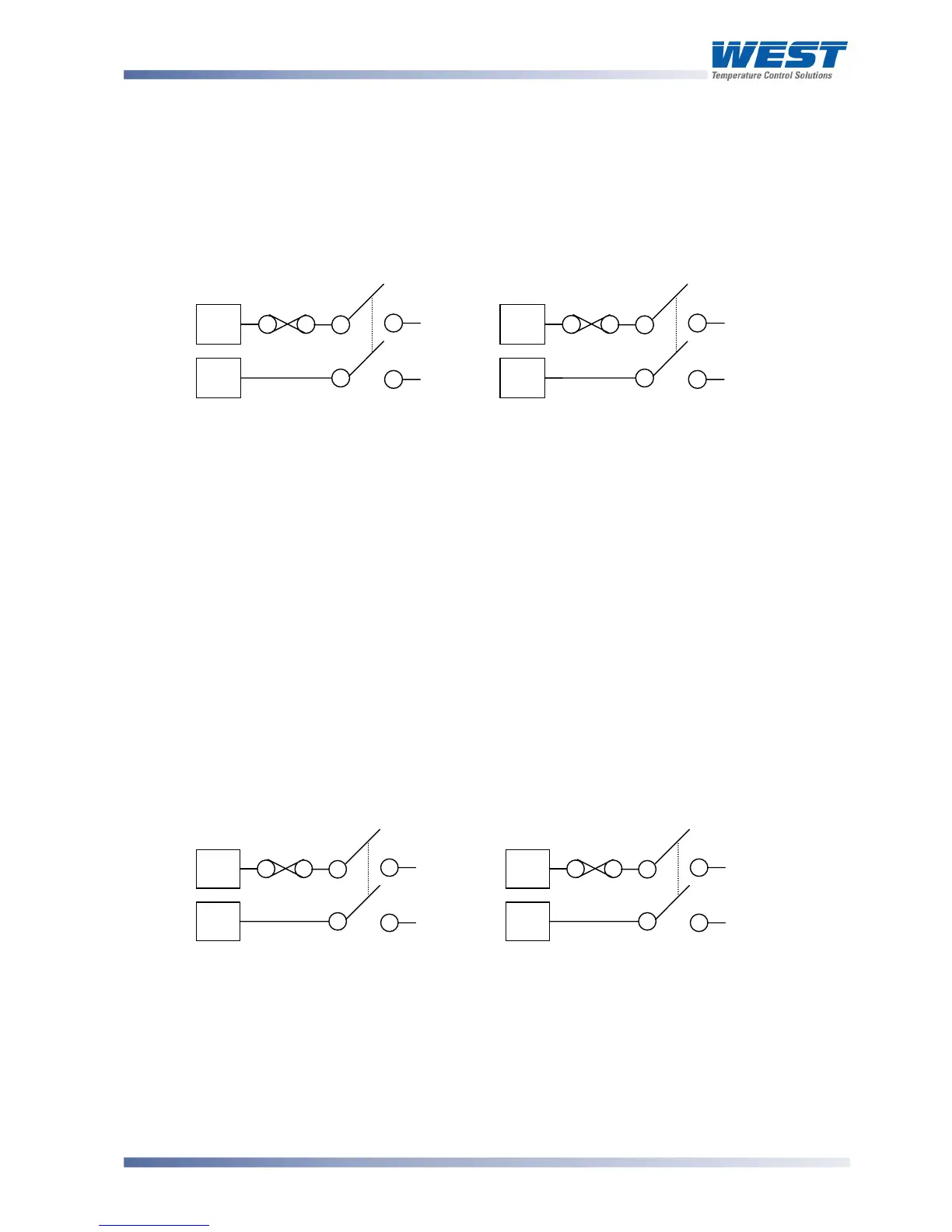
Power Connections - Mains Powered Instruments
Mains powered instruments operate from a 100 to 240V (±10%) 50/60Hz supply. Power
consumption is 7.5VA. Connect the line voltage (live and neutral) as illustrated via a two-pole
isolating switch (preferably located near the equipment) and a 1amp anti-surge fuse. If the
instrument has relay outputs with contacts carrying mains voltage, it is recommended that
the relay contacts supply should be switched and fused in a similar manner, but should be
separate from the instruments mains supply.
1
/
16
DIN
1
/
4
DIN &
1
/
8
DIN
Figure 13. Mains Power Connections
WARNING:
CHECK THE INFORMATION LABEL ON THE CASE TO DETERMINE THE CORRECT
VOLTAGE BEFORE CONNECTING TO A LIVE SUPPLY.
CAUTION:
This equipment is designed for installation in an enclosure that provides adequate
protection against electric shock
Power Connections - 24/48V AC/DC Powered Instruments
24/48V AD/DC powered instruments will operate from a 20 to 48V AC or 22 to 55V DC
supply. AC power consumption is 7.5VA max, DC power consumption is 5 watts max.
Connection should be via a two-pole isolating switch (preferably located near the equipment)
and a 315mA slow-blow (anti-surge type T) fuse.
1
/
16
DIN
1
/
4
DIN &
1
/
8
DIN
Figure 14. 24/48V AC/DC Power Connections
WARNING:
CHECK THE INFORMATION LABEL ON THE CASE TO DETERMINE THE CORRECT
VOLTAGE BEFORE CONNECTING TO A LIVE SUPPLY.
∼