1
/
4
-DIN,
1
/
8
-DIN &
1
/
16
- DIN Controllers & Indicators - Product Manual
Page 16 Connections 59305, Issue 5 – March 2005
WARNING:
TO AVOID ELECTRICAL SHOCK, AC POWER WIRING MUST NOT BE CONNECTED TO THE
SOURCE DISTRIBUTION PANEL UNTIL ALL WIRING PROCEDURES ARE COMPLETED.
WARNING:
CHECK THE INFORMATION LABEL ON THE CASE TO DETERMINE THE CORRECT
VOLTAGE BEFORE CONNECTING TO A LIVE SUPPLY.
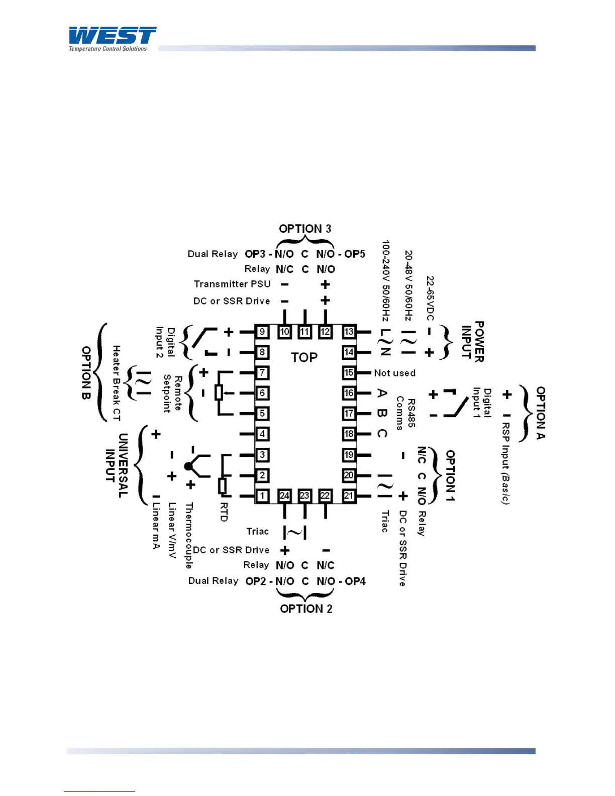
Note:
The wiring diagram below shows all possible combinations. The actual connections
required depend upon the features available on the model and the modules and options
fitted.
Figure 12. Rear terminals (
1
/
4
-DIN &
1
/
8
-DIN Instruments)