1
/
4
-DIN,
1
/
8
-DIN &
1
/
16
- DIN Controllers & Indicators - Product Manual
Page 24 Connections 59305, Issue 5 – March 2005
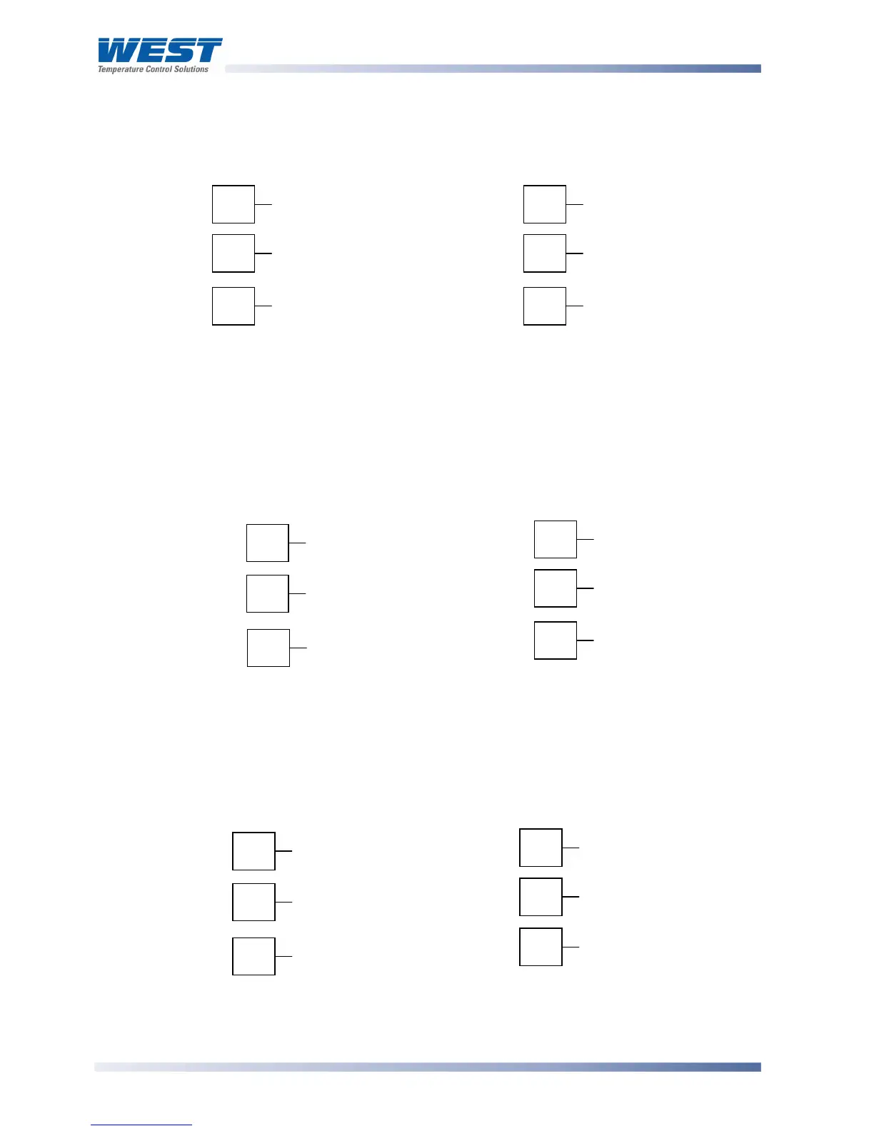
Option Slot 3 - Relay Module
If option slot 3 is fitted with a relay output module, make connections as illustrated. The
contacts are rated at 2 amp resistive 120/240 VAC.
1
/
16
DIN
1
/
4
DIN &
1
/
8
DIN
Figure 27. Option Slot 3 - Relay Module
Option Slot 3 - SSR Driver Module
If option slot 3 is fitted with an SSR driver output module, make connections as illustrated.
The solid-state relay driver is a 0-10V DC signal; load impedance must be no less than 500
ohms. SSR driver outputs are not isolated from the signal input or other SSR driver outputs.
1
/
16
DIN
1
/
4
DIN &
1
/
8
DIN
Figure 28. Option Slot 3 - SSR Driver Module
Option Slot 3 - Linear Voltage or mADC module
If option slot 3 is fitted with a DC linear output module, make connections as illustrated.
1
/
16
DIN
1
/
4
DIN &
1
/
8
DIN
Figure 29. Option Slot 3 - Linear Voltage & mADC module
10
11
_
12
+
16
17
_
18
+
10
11
_
12
+
16
17
_
18
+
10
11
N/C
COM
12
N/O
16
17
N/C
COM
18
N/O