1
/
4
-DIN,
1
/
8
-DIN &
1
/
16
- DIN Controllers & Indicators - Product Manual
Page 20 Connections 59305, Issue 5 – March 2005
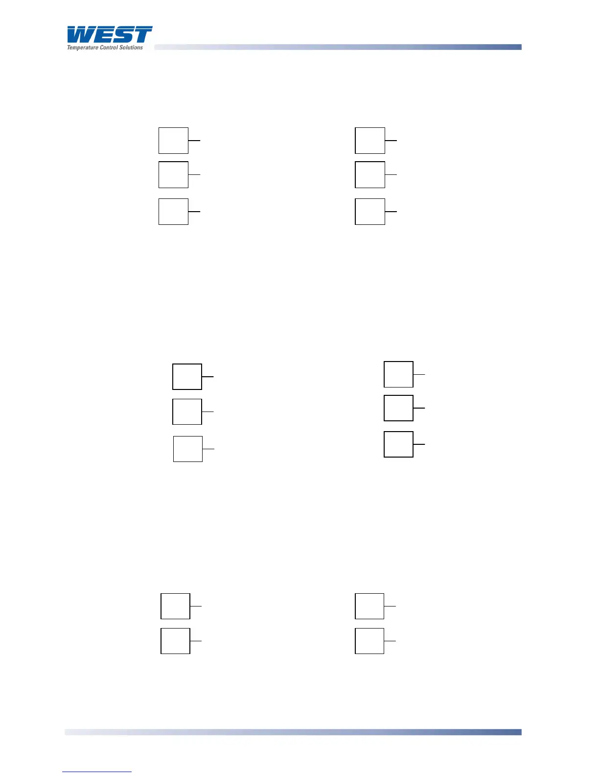
Option Slot 1 - Relay Module
If option slot 1 is fitted with a relay output module, make connections as illustrated. The relay
contacts are rated at 2 amps resistive, 120/240 VAC.
1
/
16
DIN
1
/
4
DIN &
1
/
8
DIN
Figure 18. Option Slot 1 – Relay Module
Option Slot 1 - SSR Driver Module
If option slot 1 is fitted with an SSR driver output module, make connections as illustrated.
The solid-state relay driver is a 0-10V DC signal, load impedance must be no less than 500
ohms. SSR driver outputs are not isolated from the signal input or other SSR driver outputs.
1
/
16
DIN
1
/
4
DIN &
1
/
8
DIN
Figure 19. Option Slot 1 - SSR Driver Module
Option Slot 1 - Triac Module
If option slot 1 is fitted with a Triac output module, make connections as illustrated. The triac
output is rated at 0.01 to 1 amp @ 240V AC 50/60Hz.
1
/
16
DIN
1
/
4
DIN &
1
/
8
DIN
Figure 20. Option Slot 1 - Triac Module
19
20
N/C
COM
21
N/O
1
2
N/O
COM
3
N/C
19
20
_
21
+
1
2
+
3
_
1
2
∼