1
/
4
-DIN,
1
/
8
-DIN &
1
/
16
- DIN Controllers & Indicators - Product Manual
Page 30 Messages & Error Indications 59305, Issue 5 – March 2005
6 Messages and Error Indications
The following displays are shown when an error occurs or a hardware change is detected.
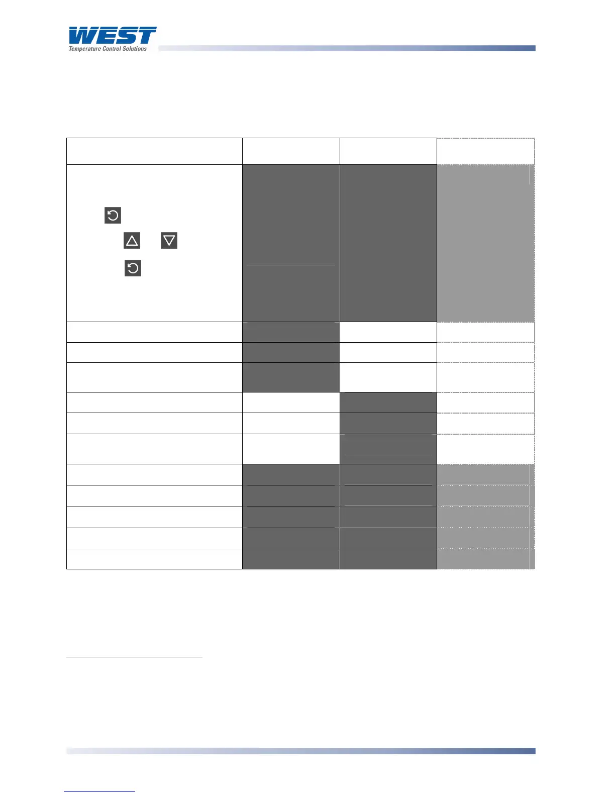
Table 4. Error/Faults conditions
Error/Faults Conditions Upper display Lower Display
(where fitted)
1
/
8
DIN Indicator
Units Display
Configuration & Setup is required.
Seen at first turn on or if hardware
configuration changed.
Press to enter Configuration
Mode,
next press or to enter the
unlock code number,
then press to proceed.
Configuration must be completed
before return to operator mode is
allowed
1
!"#"'
'
(!"#" for 1
second, then
$"%& on
Indicators)
$"%&' $'
Input more than 5% over-range
2
())*'
Normal Display Normal Display
Input more than 5% under-range
3
(++*'
Normal Display Normal Display
Sensor Break. Break detected in
the input sensor or wiring
,-./'
Normal Display Normal Display
RSP input over-range
Normal Display
())* **
n/a
RSP input under-range
Normal Display
(++* **'
n/a
RSP Break. Break detected in the
remote setpoint input
Normal Display
,-./ **'
n/a
Option 1 module fault.
.00* ,1%2' 2'
Option 2 module fault.
.00* ,1%3' 3'
Option 3 module fault.
.00* ,1%4' 4'
Option A module fault.
.00* ,1%5' 5'
Option B module fault.
.00' ,1%6' 6'
* Note
Option module number follows error legend on
1
/
16
DIN Indicators (e.g. .004)
** Note
RSP break and over/under-range indication will be seen wherever the RSP value would be
displayed.
1
This feature does not guarantee correct configuration but only helps to ensure that the unit will be
configured before use. Use of set-up mode is not enforced but may be essential for the users process.
2
If the PV display exceeds
7777
before 5% over-range is reached, an over-range indication is given.
3
Indicators will allow up to 10% under-range on non-zero based Linear ranges. If the PV display is less than
82777
before the % under-range is reached, an under-range indication is given.