1
/
4
-DIN,
1
/
8
-DIN &
1
/
16
- DIN Controllers & Indicators - Product Manual
Page 18 Connections 59305, Issue 5 – March 2005
Universal Input Connections - Thermocouple (T/C)
Use only the correct thermocouple wire or compensating cable from the probe to the
instrument terminals avoiding joints in the cable if possible. Failure to use the correct wire
type will lead to inaccurate readings. Ensure correct polarity of the wires by cross-
referencing the colours with a thermocouple reference table.
1
/
16
DIN
1
/
4
DIN &
1
/
8
DIN
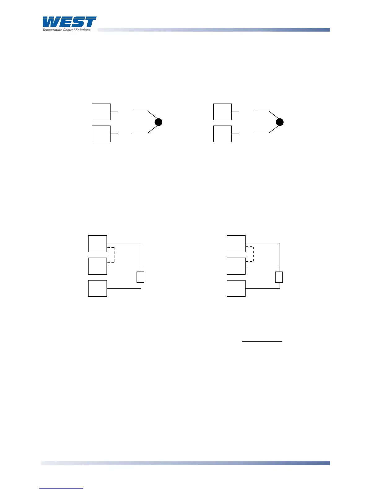
Figure 15. Thermocouple Input Connections
Universal Input Connections - RTD input
For three wire RTDs, connect the resistive leg and the common legs of the RTD as
illustrated. For a two wire RTD a wire link should be used in place of the third wire (shown by
dotted line). Two wire RTDs should only be used when the leads are less than 3 metres long.
Avoid cable joints.
1
/
16
DIN
1
/
4
DIN &
1
/
8
DIN
Figure 16. RTD Input Connections
Four wire RTD’s can be used, provided that the fourth wire is left unconnected. This wire
should be cut short or tied back so that it cannot contact any of the terminals on the rear of
the instrument.
RTD RTD
4
5
6
3
2
1
3
2
+
_
4
5
+
_