1
/
4
-DIN,
1
/
8
-DIN &
1
/
16
- DIN Controllers & Indicators - Product Manual
59305, Issue 5 – March 2005 Connections Page 25
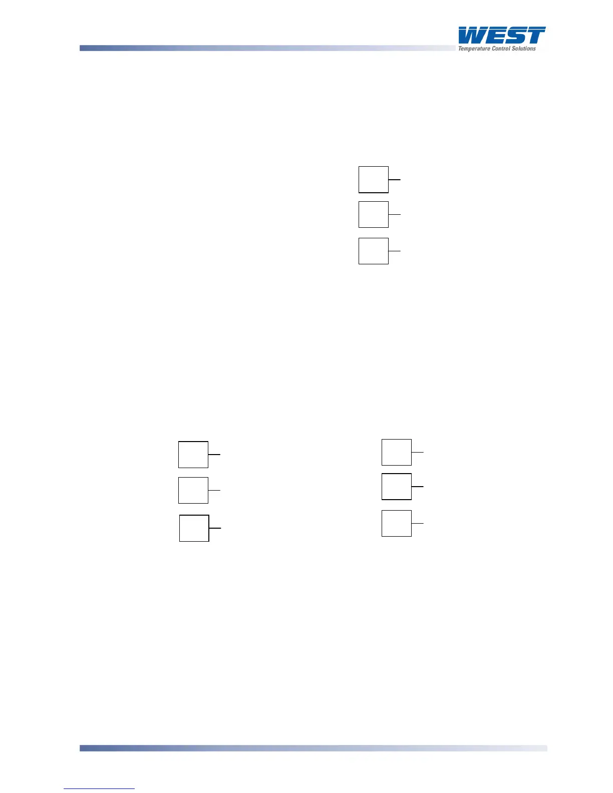
Option Slot 3 - Dual Relay Module
If option slot 3 is fitted with a dual relay output module, make connections as illustrated. This
module has two independent relays, which share a common connection terminal. The
contacts are rated at 2 amp resistive 120/240 VAC.
1
/
16
DIN
1
/
4
DIN &
1
/
8
DIN
Figure 30. Option Slot 3 - Dual Relay Module
WARNING:
THIS MODULE MUST NOT BE FITTED INTO OPTION SLOT 3 ON
1
/
16
DIN INSTRUMENTS.
Option Slot 3 - Transmitter Power Supply Module
If option slot 3 is fitted with a transmitter power supply module, make connections as
illustrated. The output is an unregulated 24V DC, 22mA supply.
1
/
16
DIN
1
/
4
DIN &
1
/
8
DIN
Figure 31. Option Slot 3 - Transmitter Power Supply Module
WARNING:
THIS MODULE MUST NOT BE FITTED INTO OPTION SLOT 2.
10
11
_
12
+
16
17
_
18
+
10
N/O OUTPUT 3
12
N/O OUTPUT 5
Option Slot 3 Dual
Relay is not available
on
1
/
16
DIN models
11
COMMON